


 1319 / 1428

STEERING
13
1.2.3.5 RACK & PINION ASSEMBLY REMOVAL
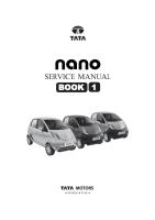
1. Loosen upper universal joint bolt. (Do not remove
the bolt).
2. Remove lower universal joint bolt and make
steering rack free from the steering column as-
sembly.
3. Remove both front wheels (Refer wheel removal
procedure / Wheels and tyres group).
4. Remove tie rod ball joint nyloc nut.
5. Remove tie rod end by using tie rod ball joint puller.
(Part No. 265458903304).
NOTE:
Steeringarmshouldnot be hammered for removal of
tie rod outer ball joints as thismay lead to damage of
steering arm part.
6. Follow steps (5) and (6) to remove tie rod ball joint
from other side.
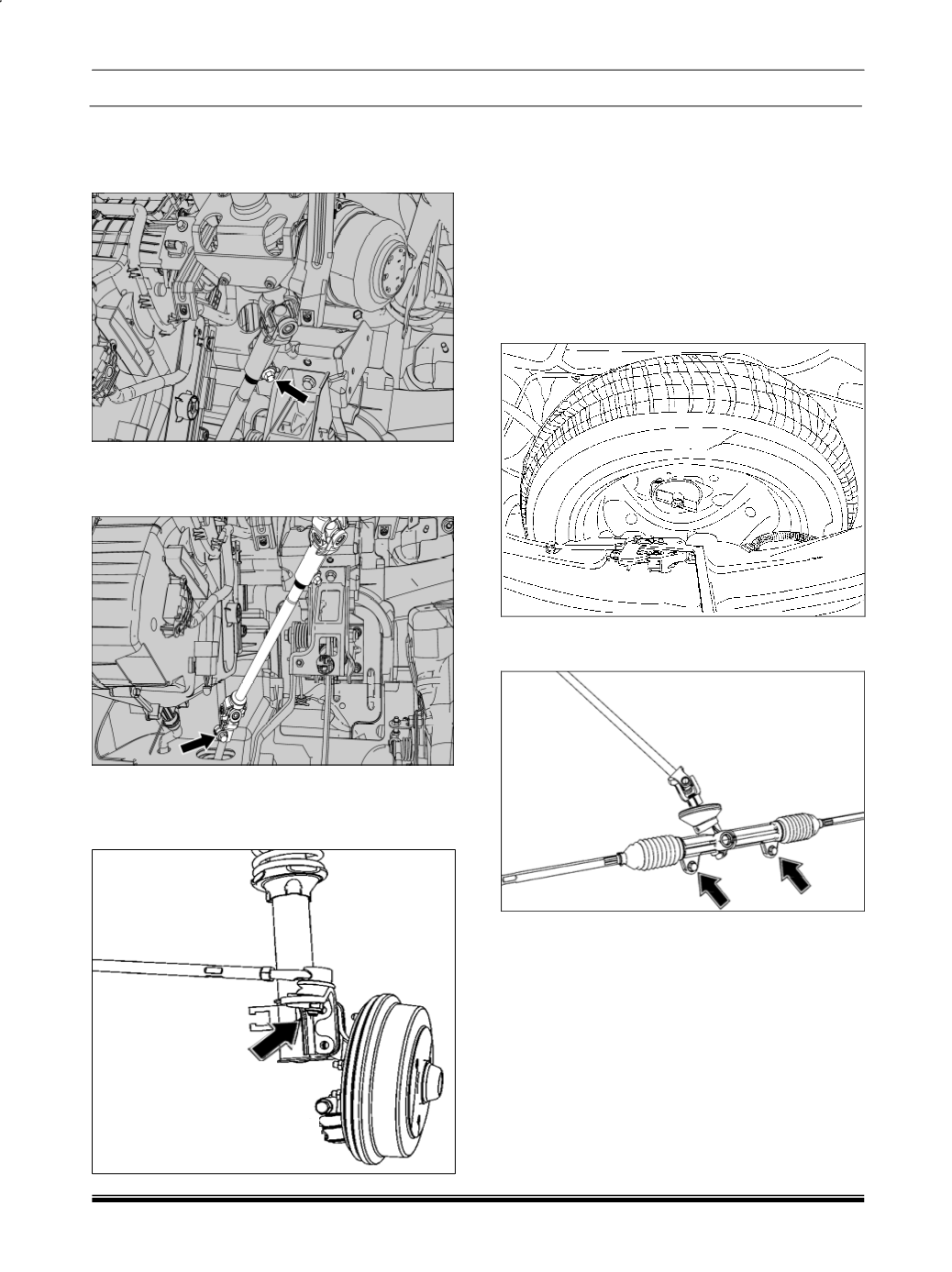
7. Unscrew spare wheel knob and remove spare
wheel.
8. Remove two mounting bolts of steering rack and
pinion assembly.
9. Take out steering rack and pinion assembly from
either side of steering knuckle.
REFITMENT:
For assembly follow reverse procedure of removal.
NOTE
There is a poka-yoke provided at steering pinion to
lower and upper universal joint (UJ) mounting. The
UJ can be fitted in one direction only.
Always ensure to fit the “Pinion locator“ for proper
fitment of UJ’s.