


 1325 / 1428

STEERING
19
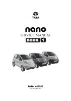
10.Apply 2 to 3 drops of Loctite to the Yoke cover
threads and tighten it to a torque of 70 kg cm. Now
unscrew the yoke cover by 30 °and 45 ° ap- proxi-
mately to achieve free pinion torque of 8 to 12 kgf –
cm.
11.Assemble the Bellow (18) on theHousing side and
secure the bellow with Bellow strap (20) and Bel-
low clip (19) as shown in the fig. Scoop Sili- con
grease using Forefinger and apply on groove of
IBJ prior to the Bellow assembly, to enable bel- low
to rotate relative to IBJ.
12.Fit the Outer Ball joints (14 & 15) on either side of
inner Ball joints.
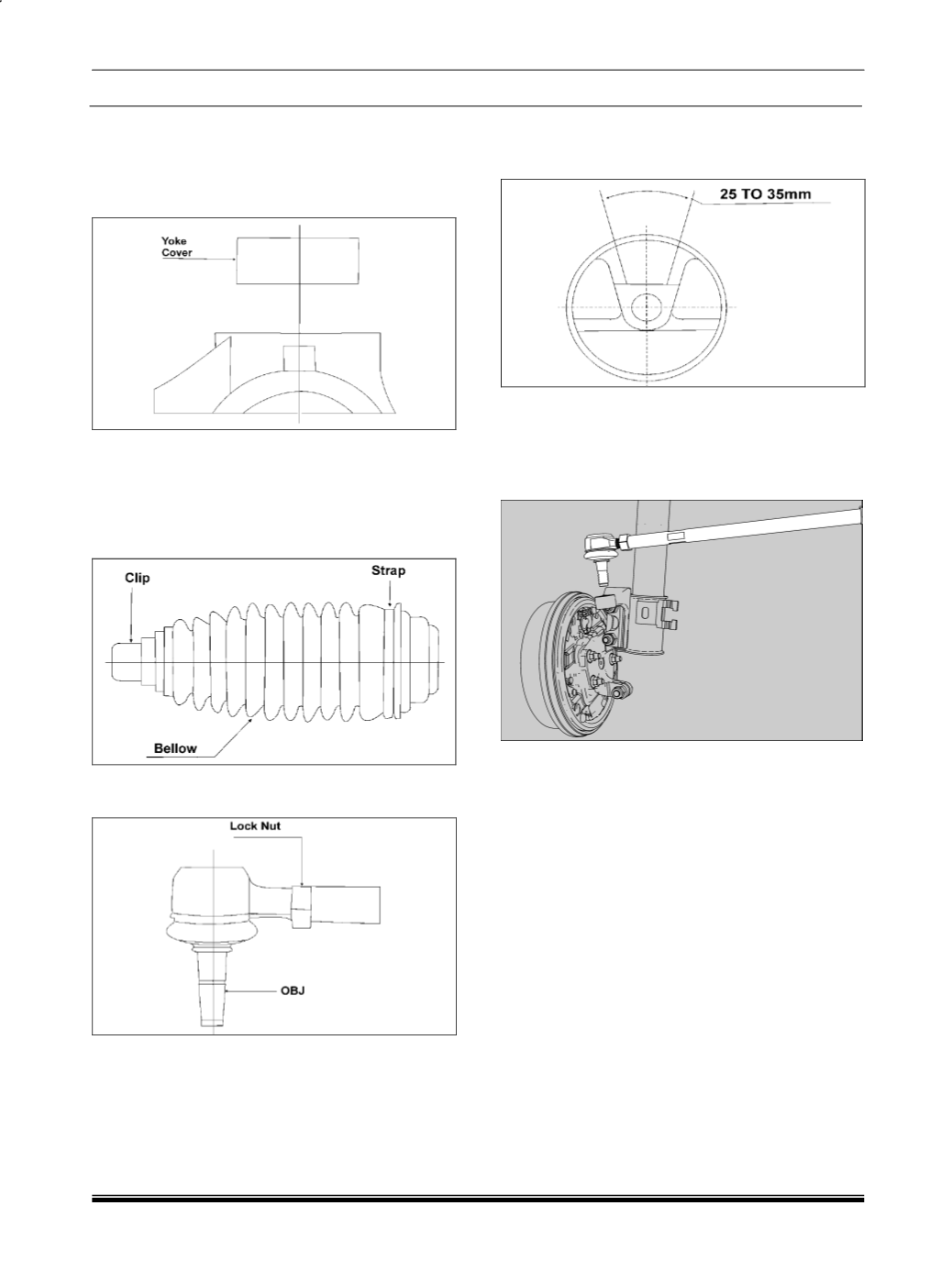
13.Check the free play of the gear at steering wheel
side. (No tyre movement when steering wheel is
turned).
1.3.3.4 OBJ ON-VEHICLE REMOVAL
NOTE
RAP need not be removed; to remove OBJ on vehi-
cle disconnect the OBJ at Steering Knuckle.
Refer on bench OBJ removal process.