


 269 / 1904

ENGINE 273 MPFI
263
ENGINE
Stand Alone Diagnosis
Refer 3.11.5 Trouble Shooting and Diagnosis.
•
Use Multimeter
•
Measure heater resistance between pin no. 1 &
pin no. 2 @ room temp. = 9 Ohm.
SystemDiagnosis
•
Use TATAdiagnostic tool.
On vehicle Removal, Inspection & Refitment
Procedure
Removal of Oxygen sensor
•
Remove the Coupler of oxygen sensor.
Precautions :
•
Ensure the coupler be unlocked while removing
the connection.
Inspection of oxygen sensor:
•
Check the heater coil resistance of the O
2
sensor.
(Refer 3.11.5 Trouble Shooting and Diagnosis.)
Precaution :
•
Ring spanner should not inserted from the
connector side.
•
Reconnect the coupler.
Precaution :
•
Ensure that the connector is properly locked.
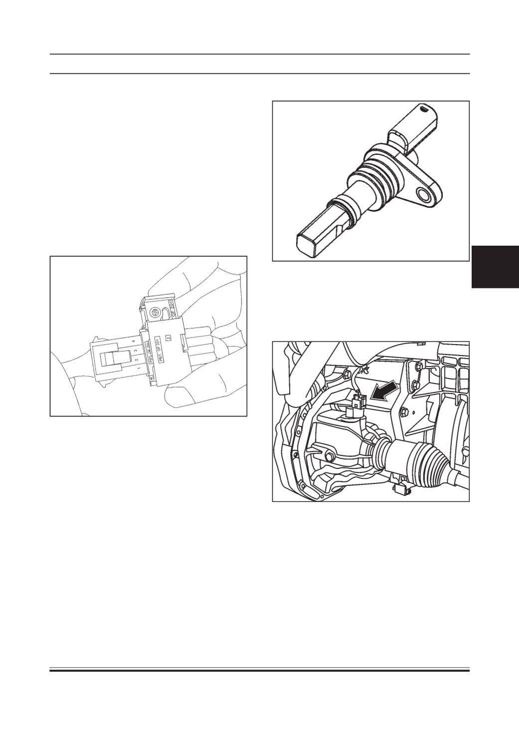
VEHICLE SPEED SENSOR
Type
Hall Effect sensor
Location:
This vehicle speed sensor is mounted on the transaxle
on speedo output location
Working Principle
This sensor is a semiconductor device, employing Hall
Effect switches. It provides On/Off pulses, when a
rotating metallic object interrupts the magnetic field.
System Integration
Vehicle speed sensor sends output pulses to cluster
for speed indication. Instrument Cluster provides
buffered output to EMS ECU. Signal transfer is 1:1