


 271 / 1904

ENGINE 273 MPFI
265
ENGINE
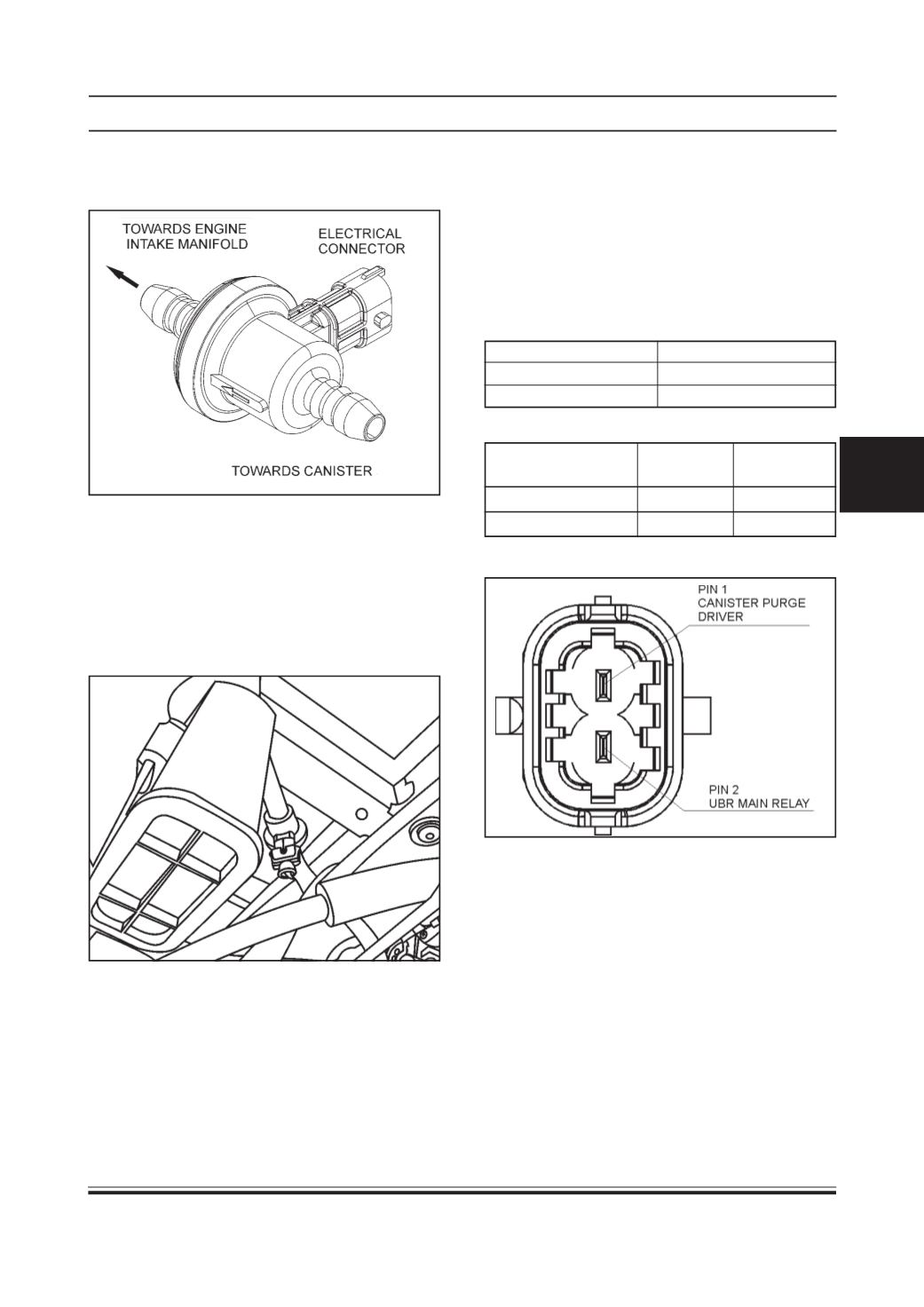
Storage and Operating Conditions
Operating Temperature -30°C to +140°C
Storage Temperature -40°C to +140°C
Max storage time
15 Years.
Pin Details
Signal
Connector ECU Pin No
Pin No.
Canister Purge Driver
1
15
UBR Main Relay
2
-
Pin Configuration
3.11.3 ACTUATORS
CANISTERPURGE VALVE
Component Information:
Type:
TEV 5
Location:
This is mounted on canister purge line between
canister & engine intake manifold. In petrol vapour
circuit this valve connects canister purge line to intake
manifold, downstream side of integrated throttle body.
Working Principle
The canister purge valve (CPV) meters the gas flow
which is generated during regeneration of the activated
carbon filter, utilized for fuel tank ventilation. The CPV
is triggered by impulses. Duration and frequency are
adjusted by an electronic unit depending on the load
of the engine.
Stand Alone Diagnosis
Refer 3.11.5 Trouble Shooting and Diagnosis.
•
Use Multimeter.
•
Solenoid coil resistance = 16 Ohm +/- 2 Ohm @
20°C.
•
Measure the resistance across pin 1 and 2.
•
Operating voltage = 9 to 16 V
SystemDiagnosis
•
Use TATAdiagnostic Tool.
On vehicle Removal, Inspection & Refitment
Procedure
(Refer Fuel System)
System Integration
Supply voltage: 9 V to 16 V (from main relay)
ECUprovides drive signal to this solenoid valve to purge
the petrol vapour from canister into the engine (inlet
manifold) at appropriate speed and load of engine as
decided by ECU. This valve is kept open (to purge)
depending upon the duty cycle ratio drive signal from
ECU.