


 213 / 1904

ENGINE 273 MPFI
207
ENGINE
•
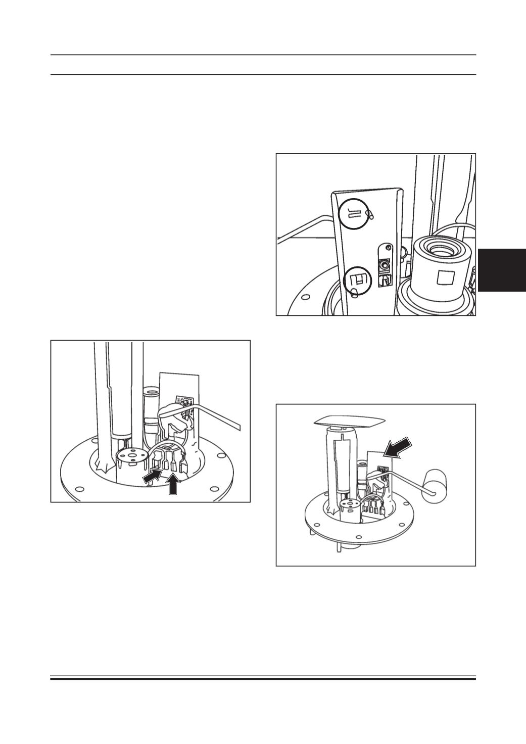
Use a flat headed screwdriver to gently ease out
the TFR housing using the gap already formed.
Pull out the clip B carefully. Then release the clipA
by pulling the upper side of TFR plate slowly and
carefully. During this complete disassembly
sequence keep the "Unclipping plate" always
pressed on the flange.
•
Scrap the dissembled faulty / damaged / failed
Level Sensor Assembly.
•
Align the suitable "Unclipping plate" on to clipping
area of flange and press the plate gently against
the flange extension. An audible unclipping sound
is heard and a gap forms between the TFR housing
and the flange in the region of "Clip A". (TFR -
Thick Fill Resistor)
•
Care should be taken not to damage the following
components/ subassemblies while assembling and
dismantling of Fuel level sensor assembly.
i. Quick Fix Connectors on Flange
ii. Electrical Connector on Flange
iii. Pressure Regulator Assembly
iv. Filter Assembly
v. Roll Over Valve (ROV)
vi. Pump Assembly
•
During the disassembly care to be taken that the
flange/mounting holes are not damaged.
•
During assembly of new level sensor assembly the
lever arm and float should not be handled.
Replacement of Fuel Level Sensor Assembly
Disassembly Procedure:
Calibration Values of Level Sensor
•
Hold the fuel supply unit upside down.
•
Carefully pull the electrical connector of the Level
sensor Assembly.
Clip B
Clip A
TFR Housing