


 212 / 1904

206
ENGINE 273 MPFI
•
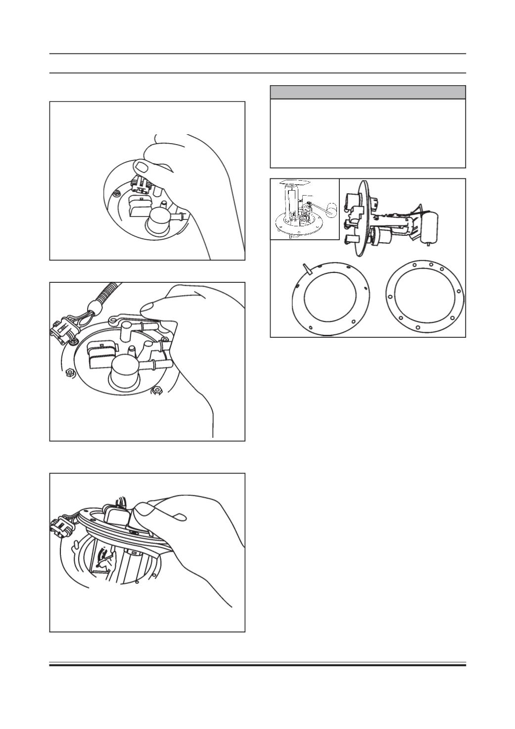
Disconnect electrical connector.
•
Unscrew the six hexagonal mounting bolts.
•
Take out the entire assembly along with cover plate
and gasket.
•
Take out the gasket and cover plate from the
assembly.
WARNING
Unless replacement is necessary, fuel module
should not be removed from the tank since the
rubber parts i.e. gasket, seals etc. may get
exposed to air, light and may become hard. Never
apply an excessive force to the fuel pump nipple or
lead wire. This may result in bend or poor contact.
2.1.Fuel Level Sensor Assembly/Float Unit
Precautions:
Following precautions should be taken during
assembly & dismantling of fuel level sensor assembly/
float unit.
•
The level sensor assembly should not be held by
lever assembly or cable assembly.
•
It has to be ensured that the fuel level sensor
assembly is assembled in a clean area,
immediately after opening the packing.
•
During installation, the float lever arm should not
be touch the sides of the tank opening.
•
Precaution to be taken to avoid dropping the unit
to avoid damage whichmight affect the functioning.
•
The lever sensor should not be directly connected
to the battery (12V).
•
Under delivery packing condition, the level sendor
assembly is already calibrated.
•
Long term storage (upto 2 years) can only be
permitted if the units have been separately packed
in air tight containers.
(This is essential for spare parts and overseas
transportation).