


 185 / 745

KRYOTEC ENGINE
177
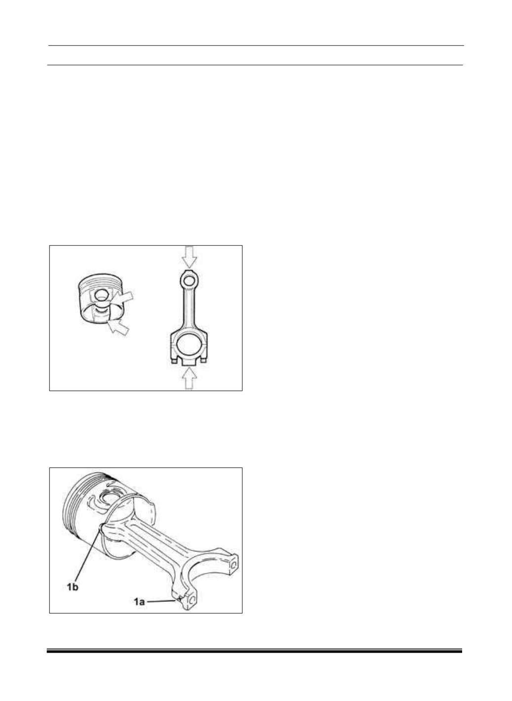
3. The arrows in the diagram illustrate where
material can be removed from to equalize the
weight.
4. Check that the weight difference between the
connecting rods, complete with half-bearings, caps
and screws is within the prescribed values (Refer
to 09 - Engine/Specifications).
5. The arrows in the diagram illustrate where
material can be removed from to equalize the
weight.
6. Fit the piston rings on the pistons using the tool.
7. Join the connecting rods to the pistons so that
the number printed on connecting rod head (1a) is
facing notch (1b) on the piston skirt for the oil jet
housing.
8. Fit the pins and secure them using the circlips.
9. Combine the connecting rods relative to the
pistons so that the number stamped on the
connecting rod head (1a) is facing the notch (1b)
formed on the skirt of the piston to the housing of
the oil jet.
10. Insert the pins and secure with its snap rings.