


 162 / 745

KRYOTEC ENGINE
154
journals: the first two numbers on the left refer to
the first journal on the timing side.
• For the identification of the class of journals you
should refer to the numerical code of reference (2).
• In the case of the example, numbers 11111N
indicate that all five pins are Class A (red).
43. Another method of identifying the class of the
pins is to read the reference (3).
In the case of the number 94 (the first on the left)
corresponds to the dimensional value of 52.994 of
the first journal that identifies the Class A (red
color). The same method should be applied to
other groups of two figures (97 - 95 - 95 - 94).
BEARING CLASS
• Crankshaft journal class A (normal), 52.994-
53.000 mm, RED, code 1 (94 00) *
• Crankshaft journal class B (normal), 52.988-
52.994 mm, BLUE, code 2 (88 94) *
• Crankshaft journal class C (normal), 52.982-
52.988 mm, YELLOW, code 3 (82 88) *
• Crankshaft journal class D (refinished 0.127 mm),
52.867-52.873 mm, BROWN, code 6 (67 73) *
• Crankshaft journal class E (refinished 0.127 mm),
52.861-52.867 mm, GREEN, code 7 (61 67) *
• Crankshaft journal class F (refinished 0.127 mm),
52.855-52.861 mm, BLACK, code 8 (55 61) * (*):
Last two numbers (part thousandth) is the size of
the main journals.
NOTE
When using a crankshaft which has been
refinished to the maximum value of 0.127 mm by
the operation of grinding and lapping, the class
must be chosen by means of dimensional
measurement of the pin diameter as previously
described.
The clearance between journal and bearing shell,
obtained by the selection method indicated above,
must be within the following values: Minimum:
0.011 mm - Maximum: 0.071 mm. This value may
be measured, as a final check, using the calibrated
wire (Plastic Gauge).
44. Install the lower bearing shells in the engine
block.
45. Install the crankshaft onto the bearing shells in
the engine block.
NOTE
The main bearing caps have engraved notches
(zero to four from the front of the engine) which
define the mounting position.
46. Install the upper bearing shells into the bearing
caps and install the bearing caps.
47. Tighten the bearing cap bolts using a suitable
angle tightening tool to the proper (Torque
Specifications).
48. Install the 1860815000 crankshaft rotation tool.
49. Rotate the crankshaft with the tool until the
affected cylinder is at BDC.
NOTE
:
Position the rod and piston in the engine block so
that the discharge on the skirt of the piston is
aligned with the oil jet mounted on the engine
block.
Select the appropriate bearing shell class based on
the following measurement procedure.
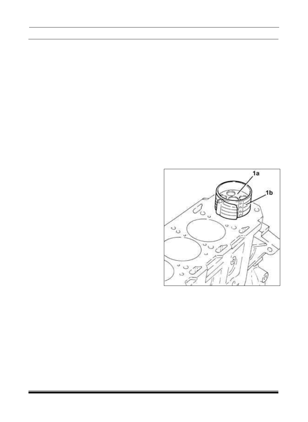
50. Install the rod and piston (1a) complete with
bearing shell using a ring compressor (1b).
51. Repeat the proceeding steps for installation of
the remaining rod and piston assemblies into the
engine block.