


 3891 / 4910

{Osprey CCM}
DTC Troubleshooting Data
Version: 2.0
Date: 28-Jul-17
Author: ERC
Page: 75 of 244
Copyright ©
TATA MOTORS Ltd.
This document must not be used in any way, such as copying and redistributing to third parties, without the consent of author.
DTC’s confirmation:-
After rectification, Press AC button from control Panel ensure the following points by AC parameters using TML
diagnostic tool before handing over to customer.
a) Physical check of temperature change when requested.
b) Read ECU parameters 4A45, which should be requested values.
Circuit Schematic Diagram:-
“Refer the circuit schematics from the tool”
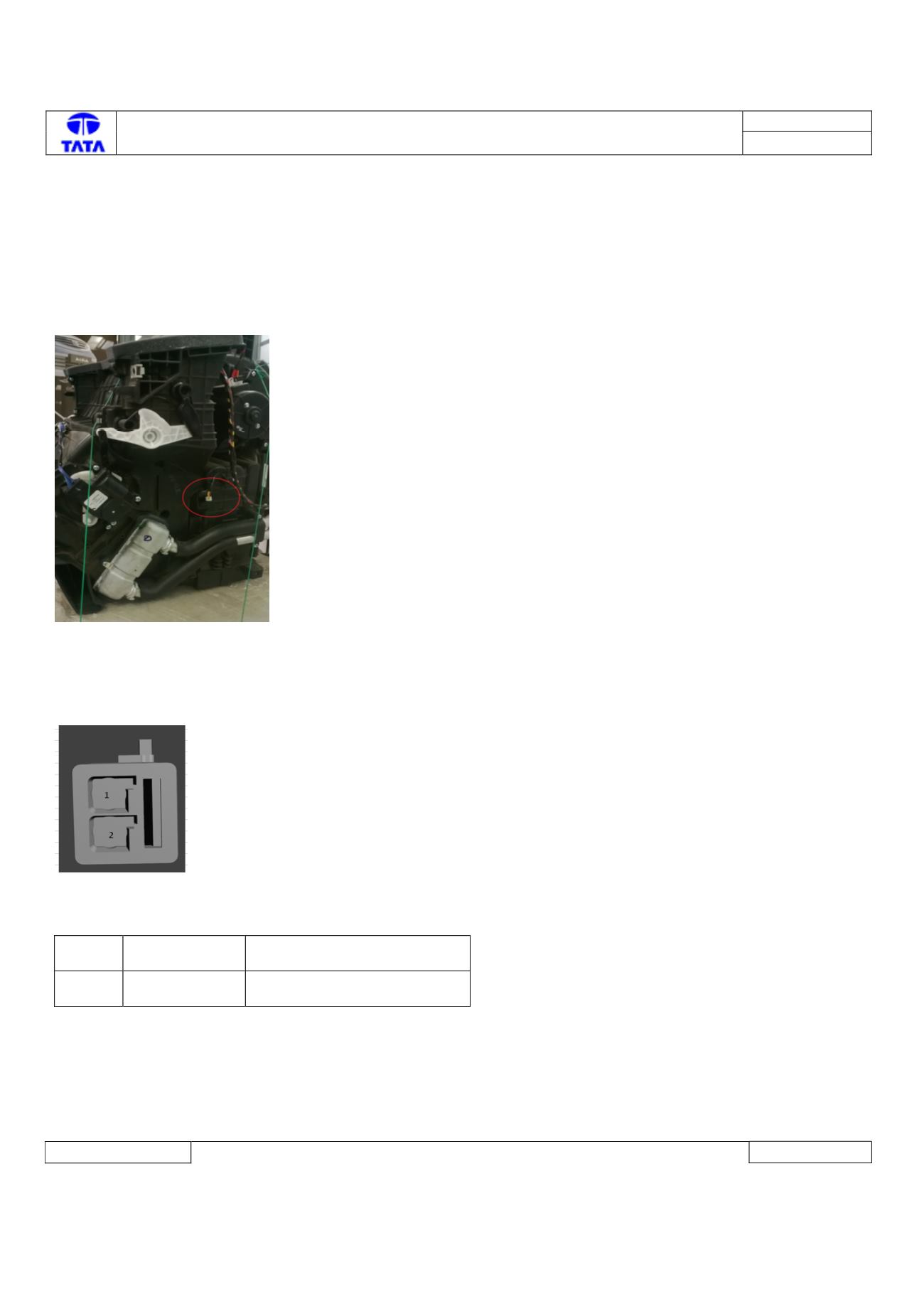
Connector Location: -
HVAC kit
Connector View & Information: -
Pin Details:-
1
EVAPSensSig
Sensor Temperature
Evaporator Signal
2
EVAPSensGnd
Sensor Temperature
Evaporator Gnd
Inspection Method: -
1) If there is no continuity between the sensor connector & ECU connector then correct the wiring harness
2) If there is a continuity between the sensor signal and battery lines correct the wiring harness (wiring harness short to
battery)