


 3897 / 4910

{Osprey CCM}
DTC Troubleshooting Data
Version: 2.0
Date: 28-Jul-17
Author: ERC
Page: 81 of 244
Copyright ©
TATA MOTORS Ltd.
This document must not be used in any way, such as copying and redistributing to third parties, without the consent of author.
DTC’s confirmation:-
After rectification, Press Fresh/Recirc button from control panel ensure the following points by using TML diagnostic tool
before handing over to customer.
a) Physical check of Fresh Recirc Parameters change when requested.
b) Read ECU parameter
Fresh Air/RECIRC Feedback Power Supply
, which should be requested values.
Circuit Schematic Diagram:-
“Refer the circuit schematics from the tool”
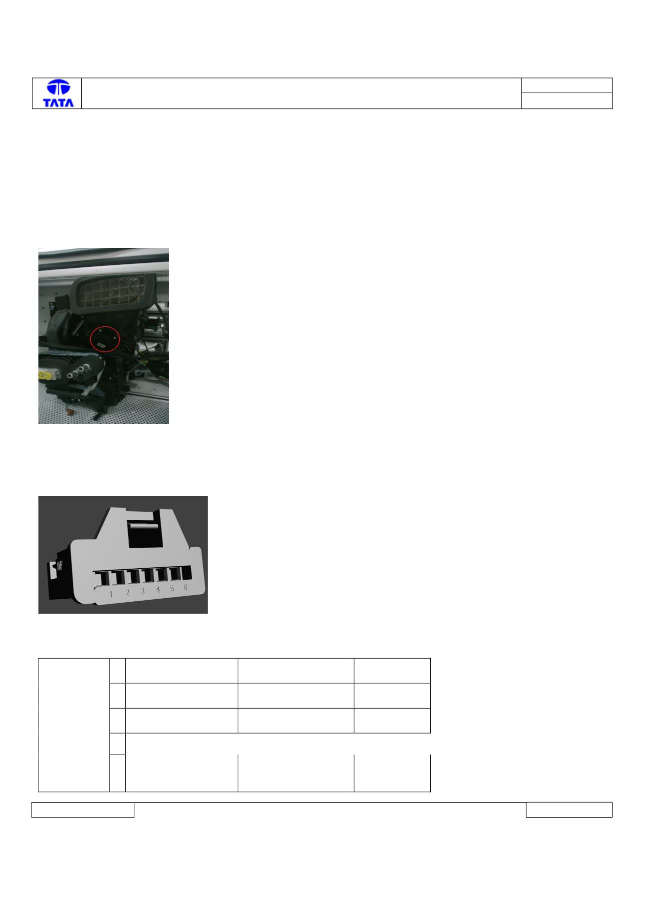
Component Location & Image:-
Connector Location: -
HVAC kit
Connector View & Information: -
Pin Details:-
C1
ACTUATOR
Amp no 0-
1355082-1
1
PotentiometerGnd
Potentiometer
Ground with FB-
Gnd
2
PotentiometerFbSig
Potentiometer
feedback signal
Analog
3
PotentiometerSpply
Potentiometer
Supply with FB-
Power
4
5
Mot +
Motor signal is + in
CW and Motor
signal is - in CCW
Digital