


 508 / 1232

DRIVETRAIN C549
33
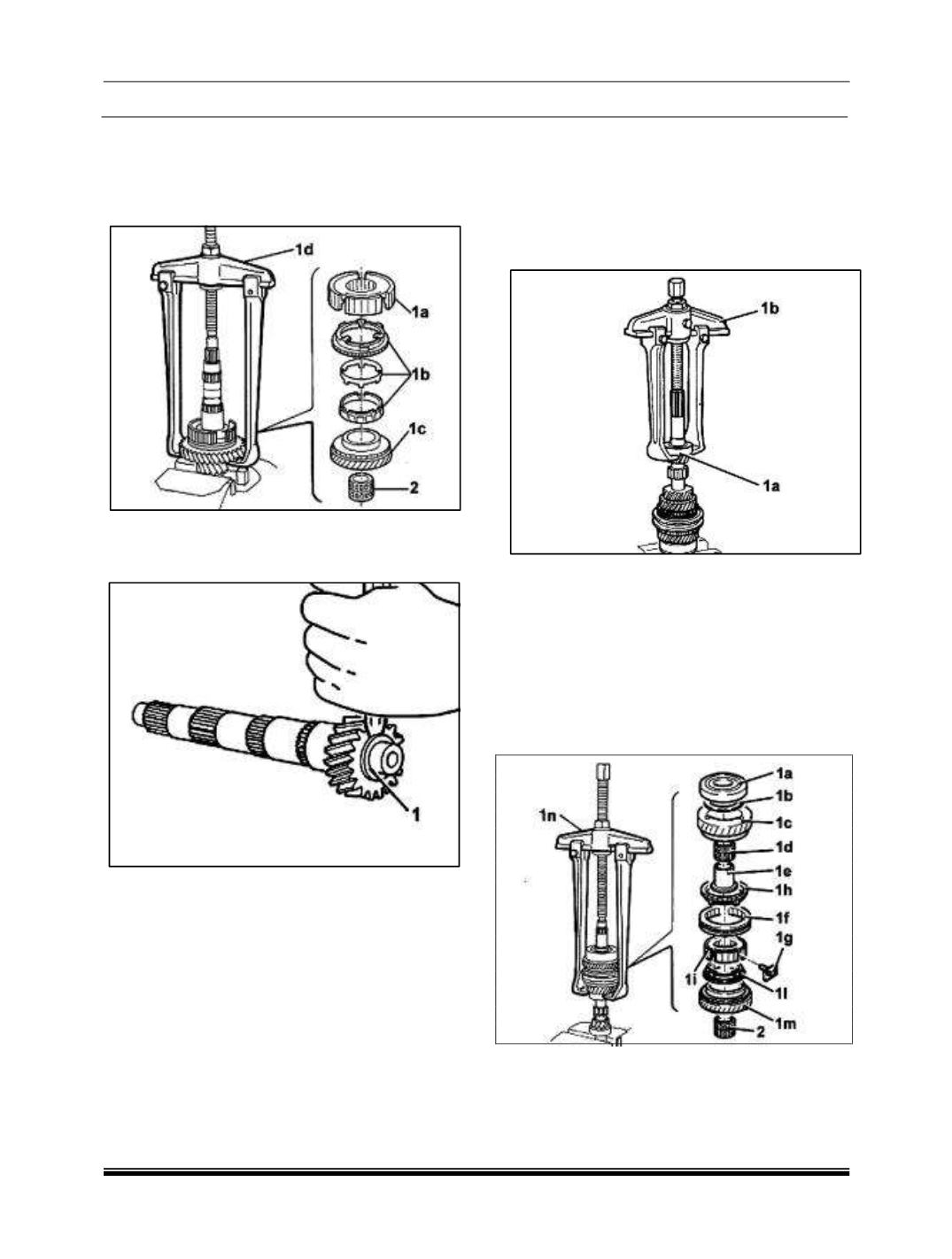
8. Remove the 1st-2nd and reverse sliding
sleeve. Hub (1a), the 1st speed synchronizer
ring assembly (1b) and 1st speed drive gear
(1c) using tools (1d)287458902606(Extractor)
and (1e) 287458902608 (Clamps).
9. Remove the needle bearing (2).
10.Move the lay shaft front bearing inner race, as
necessary, using a special chisel.
11.Remove the inner race of the lay shaft front
bearing using the tools 287458902604 (Strut)
and287458902615 (Clamps).
NOTE: If
the lay shaft front bearing inner race
has to be replaced and cannot be removed,
replace it together with the lay shaft.
E. MAINSHAFT- DISMANTLING
1. Move the main shaft front bearing, as
necessary, by applying a special chisel to the
inner race.
2. Remove the main shaft front bearing (1a)
using tools (1b) 287458902604 (Strut) and (1c)
287458902615 (Clamps).
3. Remove rear bearing (1a), shim (1b), 4th
speed drive gear (1c), 4th speed drive gear
needle bearing (1d), 4th speed drive gear bush
(1e), 3rd and 4th speed sliding sleeve (1f), pre-
synchronizer pads (1g) for the 3rd and 4th
speed sliding sleeve hub, 4th speed
synchronizer ring (1h), hub for the 3rd and 4th
speed sliding sleeve (1i), 3rd speed
synchronizer ring (1l) and third speed drive
gear (1m) using tools (1n) 287458902606
(Extractor) and (1o) 287458902608 (Clamps).
4. Remove the needle bearing for the 3rd speed
drive gear.
5. Proceed with washing and checking the
condition of all the components