


 504 / 1232

DRIVETRAIN C549
29
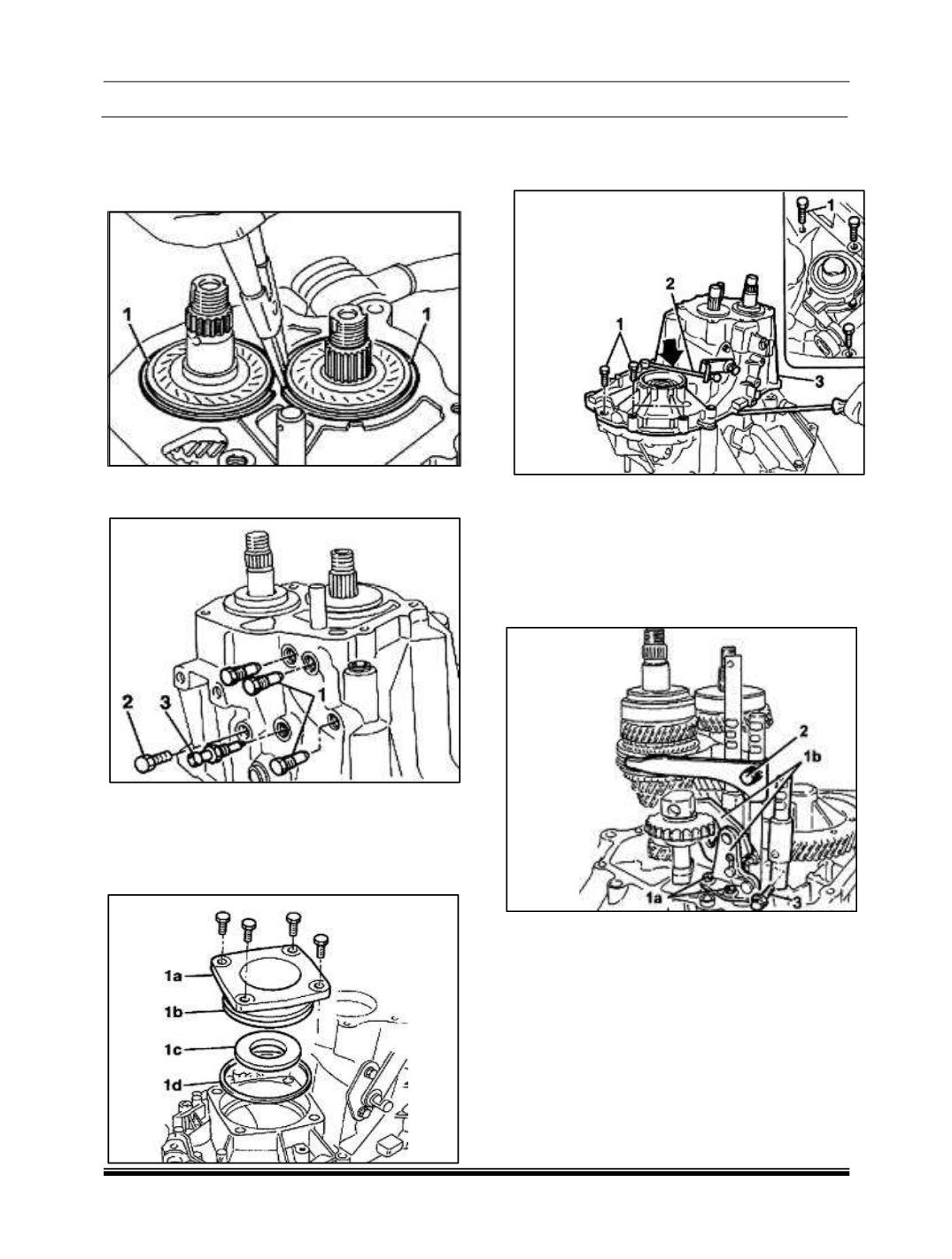
C. REMOVAL OF SHAFTS, CONTROL RODS
AND DIFFRENTIAL
1. Remove the main and lay shaft rear bearing
circlips (1).
2. Unscrew the plugs (1) for positioning the gear
control rods.
3. Unscrew the reverse shaft fixing bolt (2).
4. Unscrew the reversing light switch (3).
5. Unscrew the fixing bolts and remove the
differential flange (1a) complete with O-ring
(1b), oil seal (1c) and scraper ring (1d).
6. Unscrew the bolts (1) fixing the TRANSAXLE
casing to the manual TRANSAXLE and
engine support.
7. Position the gear elector/engagement lever
(2) downwards.
8. Remove the TRANSAXLE casing (3) using
two Screwdrivers for leverage by the special
projections provided on housings.
9. Unscrew the bolts (1a) and remove the
reverse fork mounting bracket (1b).
10. Unscrew the 3rd-4th speed fork screw (2).
11. Unscrew the 1st-2nd speed drive fork bolt (3).