


 503 / 1232

DRIVETRAIN C549
28
6. Remove the 5th speed driven gear (2).
7. Remove the 5th speed synchronizer rollers
(3) and springs retaining flange.
8. Remove the 5th speed control fork (4).
9. Remove the Reverse engagement sliding
sleeve (5).
10. Remove the pre-synchronizer (6) mountings.
11. Remove the 5th speed engagement sliding
sleeve (7).
12. Remove the 5th speed synchronizer ring (8).
13. Remove the 5th speed drive gear (9).
14. Remove the needle bearing for the 5th speed
drive gear (10).
15. Remove the 5th speed drive gear bush (11).
16. Unscrew the bolt (12a) and remove the main
and lay shaft rear bearing retaining plate
(12b).
17. Unscrew the bolt (12a) and remove the main
and lay shaft rear bearing retaining plate
(12b).
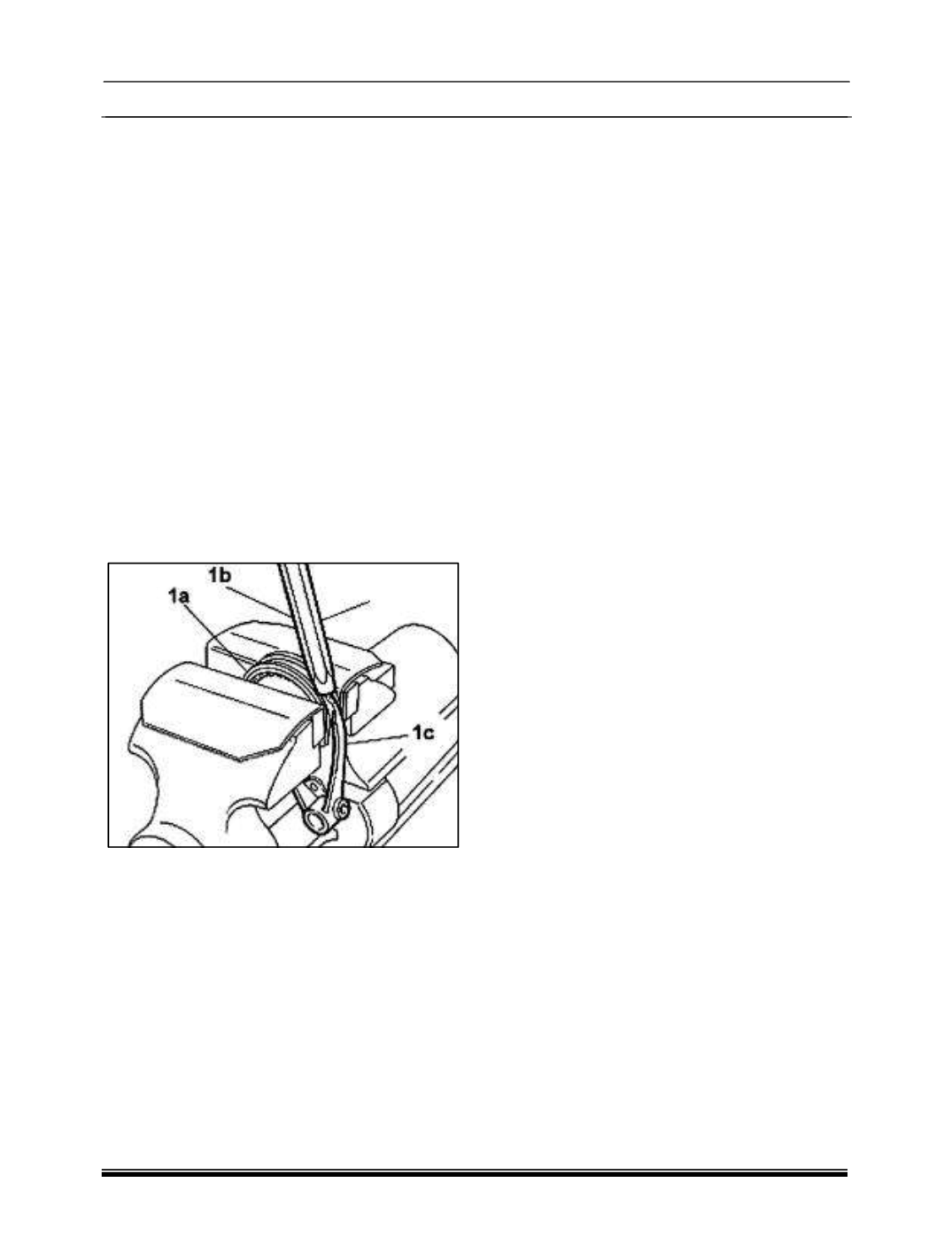
18. Lock the sleeves (1a) in the vice fitted with
19. protective plates, and then use a brass drift
(1b) alternately on the two ends of the fork
(1c) until it is released from the sleeve
WARNING
- Take care not to chip the tapered
part of the sleeve and the ends of the fork with the
drift.
NOTE:
The assembly procedure for fifth gear
assembly is given in the sub-section
TRANSAXLE ASSEMBLY
, under the head
‘FIFTH GEAR- ASSEMBLY’ to maintain the flow
of the workshop working procedure for complete
overhaul.