


 513 / 1232

DRIVETRAIN C549
38
NOTE:
Position the circlips with their
openings at the front to facilitate fitting.
23.Apply sealant to the contact surfaces between
the TRANSAXLE casing and the main and lay
shaft rear bearings retaining plate.
24. Fit the main and lay shaft rear bearings
retaining plate and secure it tightening the M8
bolt to torque 2.1 ~ 2.6 Kgm
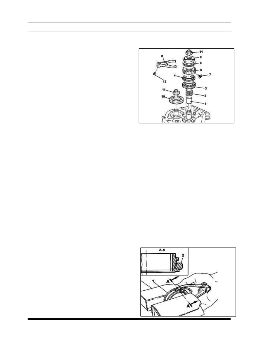
I. FIFTH GEAR - ASSEMBLY
1. Remove the 5th speed drive gear bush (1).
2. Fit the needle bearing (2) for the 5th speed
drive gear.
3. Fit the 5th speed drive gear (3).
4. Fit the 5th speed synchronizer gear (4).
5. Fit the 5th speed engagement sliding sleeve
hub (5).
6. Fit the 5th speed engagement sliding sleeve
(5).
7. Place the synchronizer mountings (7) in their
housings.
8. Fit the 5th speed control fork (8).
9. Fit the 5th speed synchronizer rollers and
springs retaining flange (9).
10.Fit the 5th speed driven gear (10).
11.Tighten the new M20 ring nuts (11) for the
main and lay shaft to a specified torque of 10 ~
12.4Kgm
12.Tighten the M6 bolt (12) for the 5th speed
control fork to the recommended torque of1.5~
1.9 Kgm.
13.Lock the sleeve (1) in a vice fitted with
protective plates;