


 1832 / 1906

HVAC
18
ii) BLOWER RESISTER AND LINEAR POWER
MODULE (
LPM)
The speed of the blower can be controlled by em-
ploying either a Blower resister or a Liner Power
Module (
LPM
). In this vehicle the blower resister is
used in models with manual HVAC and LPM is used
in models with FATC.
BLOWER RESISTER
A blower resister used in this vehicle is for a four-
speed control of blower speed. This is achieved by
having a combination of three different resistances.
The blower resister is placed in the intake air flow to
allow it to dissipate heat freely.
It is located on the lower side of the HVAC unit to the
right of the blower.
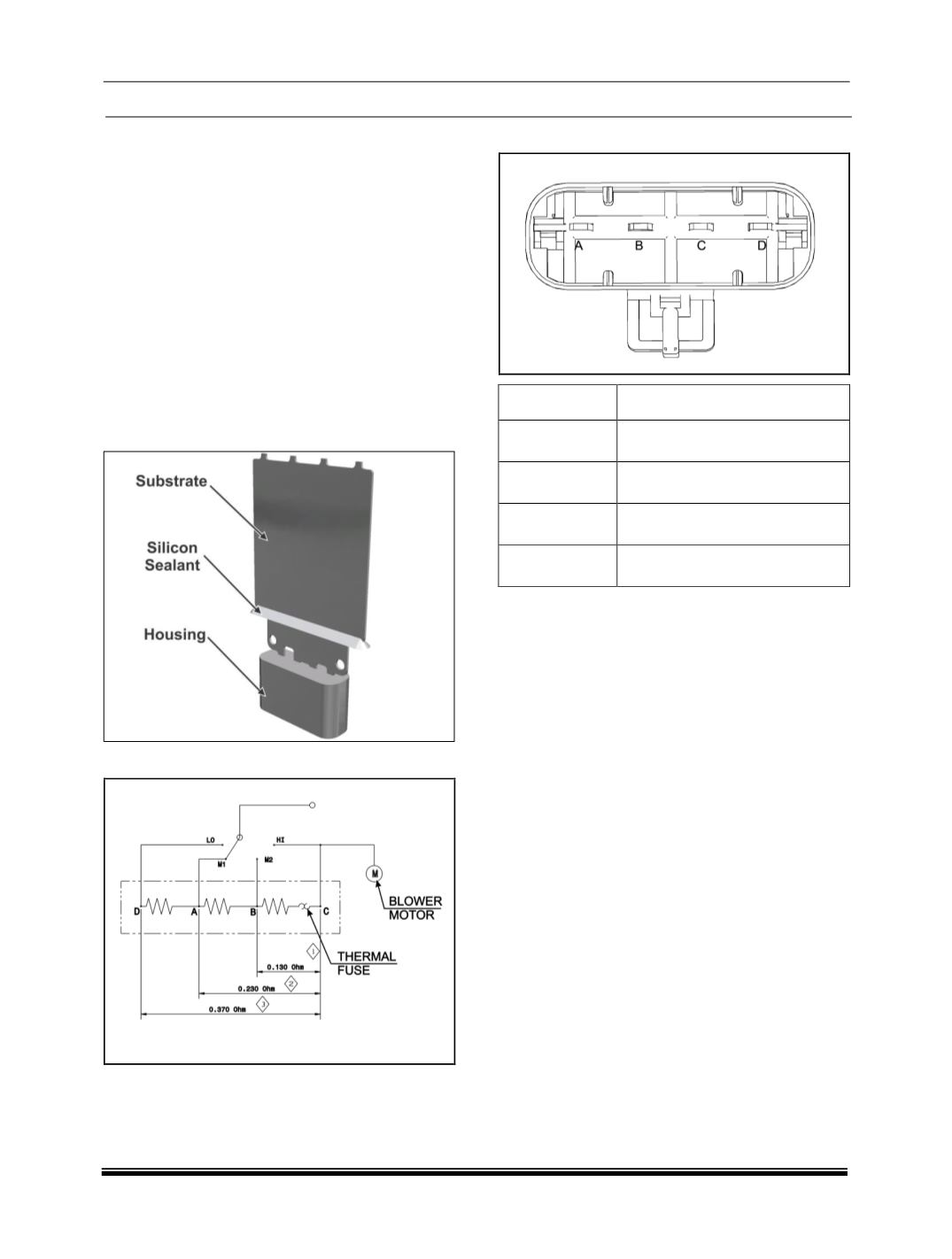
CIRCUIT DIAGRAM
PIN OUT
PIN NO
DESCRIPTION
A
Medium Low Resistance
(ML)
B
Medium High Resistance
(MH)
C
High Speed
(directly engaged)
D
Low speed resistance
INSPECTION
Measure the current at the harness side connecter at
4 speeds by rotating the blower switch. The current
measurement should as per the table below.
The resistance can also be checked. For resistance
values refer circuit diagram of blower resistor.