


 1334 / 1906

ELECTRICAL
32
described in the section "Battery”. The battery
that is used to test the output current should be
one that has been partially discharged. With a
fully charged battery, the test may not be con-
ducted correctly due to an insufficient load.
Check the tension of the alternator drive belt.
The belt tension check method is described in
the section "Inspect drive belt".
2. Turn off the ignition switch.
3. Disconnect the battery ground cable.
4. Disconnect the alternator output wire from the
alternator "B" terminal.
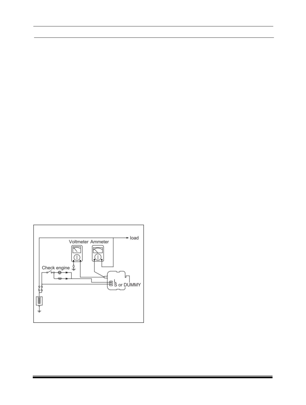
5. Connect a DC ammeter (0 to 150A) in series
between the "B" terminal and the disconnected
output wire. Be sure to connect the (-) lead
wire of the ammeter to the disconnected output
wire.
NOTE
Tighten each connection securely, as a heavy
current will flow. Do not rely on clips.
6. Connect a voltmeter (0 to 20V) between the
"B" terminal and ground. Connect the (+) lead
wire to the alternator "B" terminal and (-) lead
wire to a good ground.
7. Attach an engine tachometer and connect the
battery ground cable.
8. Leave the engine hood open.
TEST
1. Check to see that the voltmeter reads as the
same value as the battery voltage. If the
voltmeter reads 0V, and the open circuit in the
wire between alternator "B" terminal and
battery (-) terminal or poor grounding is
suspected.
2. Start the engine and turn on the headlamps.
3. Set the headlamps to high beam and the
heater blower switch to HIGH, quickly increase
the engine speed to 2,500 rpm and read the
maximum output current value indicated by the
ammeter.
NOTE
After the engine start up, the charging current
quickly drops. Therefore, the above operation
must be done quickly to read the maximum
current value correctly.
RESULT
1. The ammeter reading must be higher than the
limit value. If it is lower but the alternator
output wire is in good condition, remove the
alternator from the vehicle and test it.
NOTE
•
The nominal output current value is shown on
the nameplate affixed to the alternator body.
•
The output current value changes with the
electrical load and the temperature of the
alternator itself. Therefore, the nominal output
current may not be obtained. If such is the
case, keep the head- lamps on the cause
discharge of the battery, or use the lights of
another vehicle to increase the electrical load.
The nominal output current may not be
obtained if the temperature of the alternator
itself or ambient temperature is too high. In
such a case, reduce the temperature before
testing again.
2. Upon completion of the output current test,
lower the engine speed to idle and turn off the
ignition switch.
3. Disconnect the battery ground cable.
4. Remove the ammeter and voltmeter and the
engine tachometer.
5. Connect the alternator output wire to the
alternator "B" terminal.
6. Connect the battery ground cable.
REGULATED VOLTAGE TEST
The purpose of this test is to check that the
electronic voltage regulator controls voltage
correctly.
PREPARATION
1. Prior to the test, check the following items and
correct if necessary.
• Check that the battery installed on the