


 1331 / 1906

ELECTRICAL
29
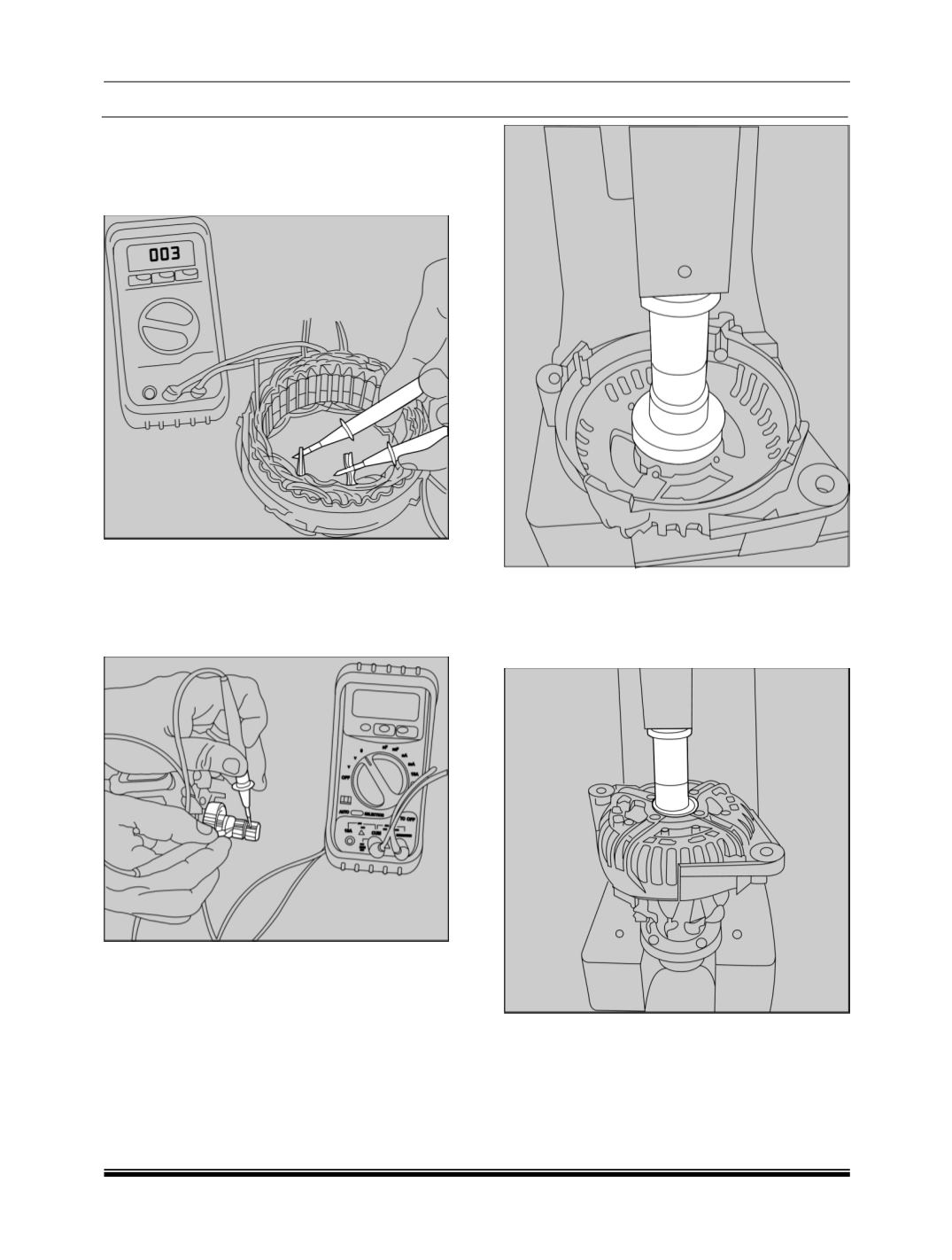
2.2 TESTING OF STATOR.
Using Multimeter, check the resistance between
the phases of the stator winding. The resistance
should be 0.040 ± 10% ohms per phase.
2.3 TESTING OF ROTOR:
Measure the resistance of the rotor winding at the
slip ring with multimeter. Resistance should be 2.1
± 10% Ohms at 20 deg c or 3 ± 10% ohms at
room temperature.
3.0 ASSEMBLY
3.1 Bearing Pressing in DEF:
If the bearing in the drive end shield (
DEF
) has
been discarded. Press in a new bearing using an
Arbor press. Assemble the bearing holding cover
late on the drive end flange using four counter
sunk screws such that the projection of the cover
plate is towards the rotor.
3.2 Rotor assembly in to the DEF:
Place the rotor as shown; put the drive end shield
on the rotor shaft as shown, press in the drive end
flange by a Spacer ring using an Arbor.
3.3 Slip ring assembly:
Press the fitting ring into the slip ring end shield,
ensuring the opening of the fitting ring towards the
mounting position of the voltage regulator.