


 1329 / 1906

ELECTRICAL
27
1.8 Fix Pulley Procedure:
Component disassembly/check
Tools required:
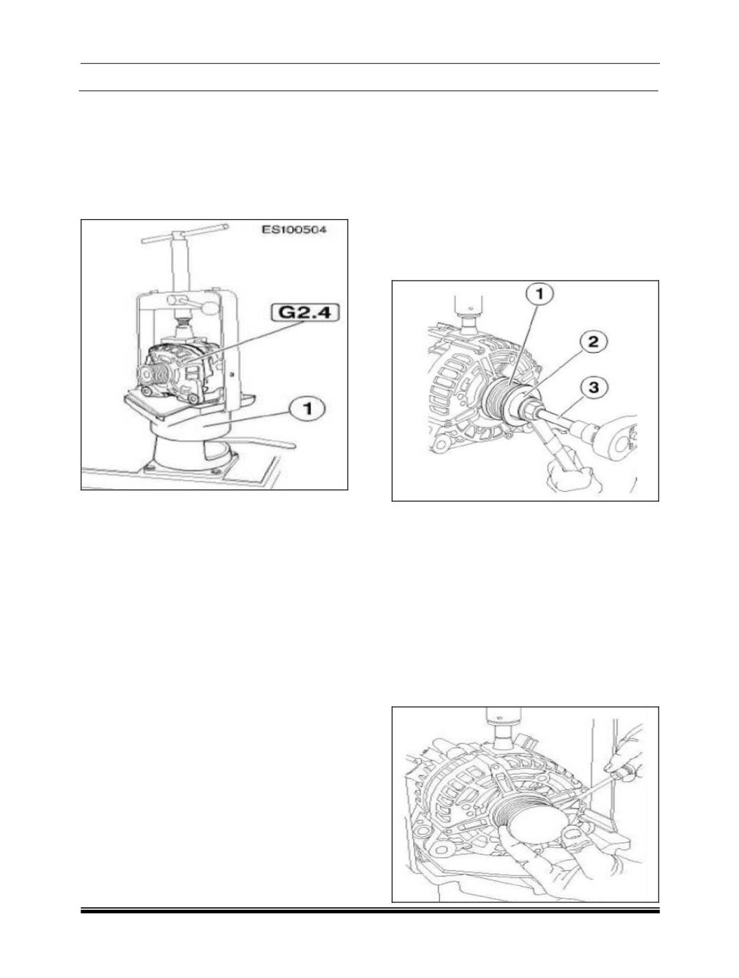
Swivel mounted clamping support: 0 986 619
362
1. Clamp component in clamping support.
1
=
Clamping support.
G2. 4 =
Compact generator.
Caution:
Take care not to damage or deform die cast
aluminum housing.
Damage or deformation may impair the
accuracy of fit of the individual components
and cause damage.
Never use any objects to block the fan when
assembling / disassembling the pulley.
2. Bent or defective fan blades will cause
damage.
3. The component <Compact generator> of
series Baseline is fitted with various pulleys:
Pulley (without cover).
Free wheel pulley (with cover).
Note:
Depending on the direction of rotation of the
component < Alternator>, the component
<Alternator rotor > and the pulley is provided with
a right-hand or left-hand thread.
< --- = Left-hand thread.
--- > = Right-hand thread
.
Remove pulley:
Tools required:
0 986 618 152 (Box spanner WAF 24), (KDLJ
6030).
Multi-point attachment M10, long.
1. Position socket wrench (2) on nut of pulley
(1).
2. Use the multi-point attachment (3) to stop the
rotor shaft, unfasten the nut using a box
wrench and detach the pulley.
Remove freewheel pulley:
Tools required:
Assembly tool: 0 986 619 396.
Multi-point socket 17*20.
1. Remove cover of freewheel pulley.
2. The cap is either clipped on or inserted.
3. Clipped-on cover can be removed using a
suitable tool.
4. Fitted cover can only be removed by piercing
and prising out.