


 805 / 1526

24
AIRCONDITIONING
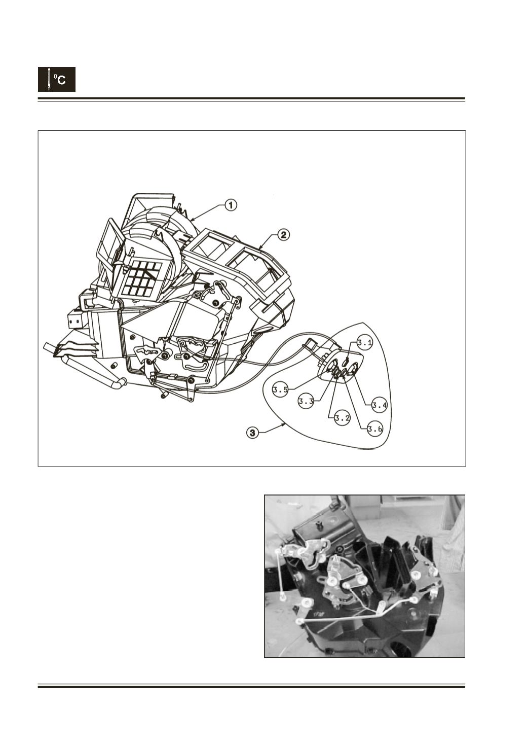
Fig. 32
6. Kinematics Assembly :
The function of the kinematics assembly is to
control the flapper’s movement and controls the
distribution of air as required at different outlets.
Fig. 31.
1. Remove the complete HVAC unit.
2. Remove the mounting screws from the
kinematics base plates.
Fig. 32.
Replace the required kinematics.
Sr. No. Part Name
1
Blower Unit
2
Cooling and heating unit
3
Control panel
3.1
Blower switch
3.2
Fresh/ recirculation switch
3.3
A/C switch
3.4
Air mode selector
3.5
Heater mode selector
3.6
Dummy
Fig. 31