


 489 / 1526

14
BRAKES
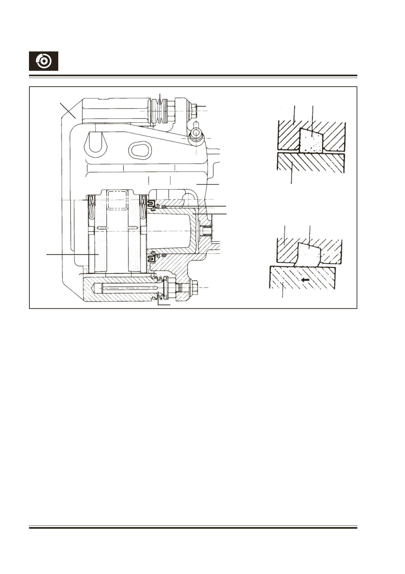
Fig. 4 - Twin pot caliper cross sectional view
Clearance Correction
When fluid pressure is applied on the piston, both
pistons move forward. The rubber seals, which exert
considerable pressure against the pistons, are fixed
into grooves in the caliper, hence the shape of the
rubber seals are distorted at the I.D. as shown in Fig.
4. When pressure is withdrawn from the brake pedal
and fluid pressure is released from the piston, a
restoring force is generated by the seals and they
push the pistons back to its original position. As the
pads wear the clearance between the disc and the
pads becomes larger, hence the pistons have to move
a larger distance. The seal then could change in shape
further but, since the seals are fixed into the grooves
in the cylinder, the distortion is limited to the same
amount as previously described. The piston moves
further to cover the distance of clearance relative to
the seal in the case. The pistons return by the same
distance and the rubber seal recover their shape as
described above and thus the clearance between the
disc and pads are maintained by adjustment
automatically.The caliper brake needs no adjustment.
CYLINDER
PISTON SEAT
(RUBBER SEAL)
PISTON
HYDRAULIC
PRESSURE ‘ON’
CYLINDER
PISTON SEAT
(RUBBER SEAL)
PISTON
HYDRAULIC
PRESSURE ‘OFF’
CARRIER
CLAIPER HOUSING
SEALING RING
PISTON
SLIDING PIN
PAD
SLIDING PIN BOOT
SLIDING PIN BOLT
Caliper Operation
When the brake pedal is pressed, the hydraulic
pressure fromMaster Cylinder pushes the pistons and
with it the in-board pad on to the disc. The caliper
body reacts and slides on the sliding pins to bring the
out-board pad into contact with the disc.The clamping
forces on both slides of the disc thus become equal.
When the hydraulic pressure is released the sealing
ring fitted in the grooves of the cylinder retracts the
pistons by a small amount which allows the moving
parts to relax sufficiently for the disc pads to retract
and remain in close proximity to disc, ready for the
next brake application.