


 290 / 1526

49
GEAR BOX G-76
ASSEMBLY OF GEAR BOX
Place shifter fork assembly 1st/2nd and Reverse/5th
over main shaft assembly at its proper place, keeping
notches towards coupling flanges side.
Place shifter fork 3rd/4th (123) alone without shaft at
its place over main shaft sleeve such that its collar is
facing outwards.
Keep counter shaft assembly aligned with main shaft.
Insert two Nos. ball (138a) in holes of shifter shaft
bore in housing. Use grease for keeping them in
position.
Fig. 94
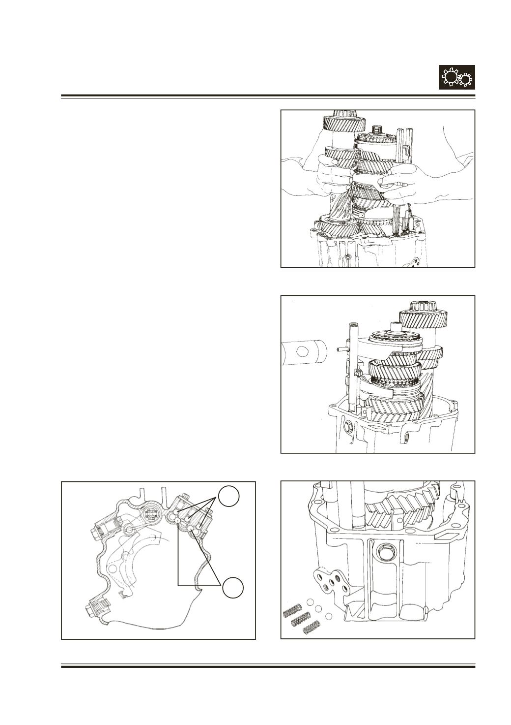
Hold and place main shaft assembly along with
counter shaft assembly and shifter fork assembly in
position in the housing - Rear.
Fig. 95
While inserting shifter shafts in the housing,
ensure
that interlocking balls are not displaced.
Fit interlock pin - 12.8 mm length (146) in shifter shaft
3rd/4th (118). Insert shaft through the shifter fork.
Align shaft with hole of fork and then press spiral pin
(124).
Fig. 96
Place 3 Nos. ball - 8 mm dia. (138) and detent spring
in holes of housing. Detent spring (142) is to lock
1st/2nd & 3rd/4th shifter shafts where as short and
stiff detent spring (141) is to be used for Reverse/5th
shifter shaft.
Fig. 97
Fix gasket (139) to detent cover (140) and tighten
hex. screws (144) along with spr. washer (145). Fit
rollers 4 Nos. (113) over pins (114) of selector shaft
(112).
Fig. 97
Fig. 96
Fig. 95
Fig. 94
Sectional View
Inter lock
balls
138
138a