


 296 / 1526

55
GEAR BOX G-76
INSTALLATION OF GEAR BOX ASSEMBLY
ON VEHICLE
Note
:Take guidelines from the write up on removal
of gear box.
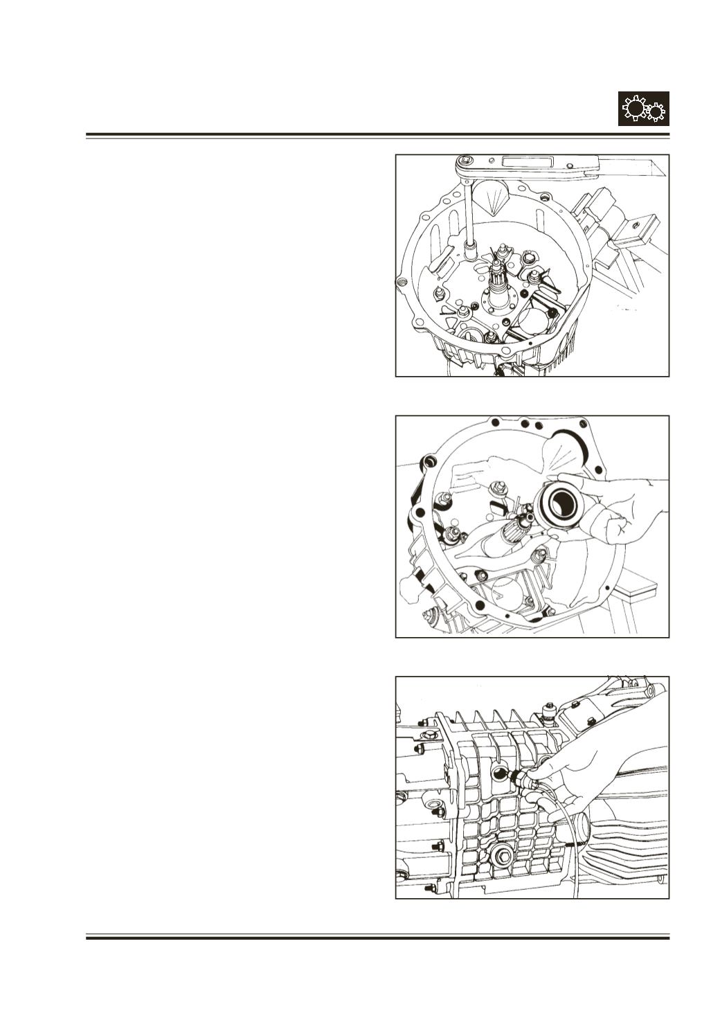
Fit clutch housing to gear box front face.
Fig. 115
Fit clutch release bearing and release fork.
Fig. 116
Lift and mount the gear box at cylinder block face,
aligning drive shaft splines with clutch plate hub
splines and clearing gear shift lever through opening
provided on the cab.
Tighten all mounting bolts of clutch housing.
Apply grease over supporting pin of extension arm
and also inside rubber bush of extension arm support.
Slide support over pin.
Fit extension arm support (164) on cross member.
Tighten nylock nut (167) along with washer (166) such
as to maintain a clearance of 10 mm between
extension arm stud end and propeller shaft.
Fit
- Clutch slave cylinder and its piping.
- Speedo cable
- Reverse indicator switch connector
Fig. 117
- Propeller shaft
Fix rubber seal in its seat over tunnel cut out and
over plate, tighten screws along with washer.
Slide rubber bellow over collar of cover plate.
Fig. 117
Fig. 116
Fig. 115