


 1459 / 1526

ELECTRICALS
37
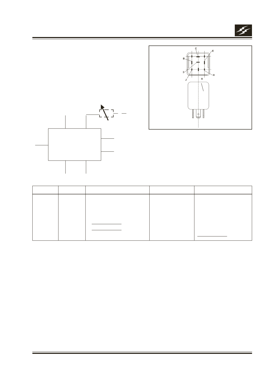
Ter. Name Ter.Type Description
Active Level
Condition
H
Input
Water level sensor
GND
Water level low
J
Input
Combi switch - wash
VCC
Sw. operated
D
Input
Combi switch - intermittent
VCC
Sw. operated
C
Input
Wiper motor park Sw. Com.
VCC/GND
Wiper moving/Wiper park
B
Supply
VCC
I/G position
E
Ground
GND
Permanent
A
Output
Park to combi switch
VCC
Fig. 44
l
l
l
l
l
l
l
l
A
D
R
+ VE 12 V
B
E
H
C
J
WIPER
CONTROLLER
17D. FRONTWIPER CONTROLLER
( Fig. 44)
Function
It generates the variable time delay during the In-
termittent wipe operation of the wipers on the
vehicle.
Location
Behind glove box on fire wall.
Connection details
Performance check
l
When the intermittent input (Ter. D) goes high,
Ter. A should get connected to Ter. B for one wipe
cycle ( The unit assumes the wipe cycle is
completed when Ter. C goes to GND from VCC
level). Then for time 't' seconds (the time should
vary from 2 to 15 second with the resister R
varying from 0 to 64 K) Ter. A and B should be
disconnected. Again Ter. A and B get connected
for one wipe cycle. This cycle continuous until Ter.
D is high.
l
When wash input (J) becomes active output Ter.
A should get connected to terminal B after 0.7
sec. and when Ter. J goes low Ter. A get disconnect
from Ter. B after 2 sec. The wash should have
higher priority than the intermittent signal.
l
When the Ter. H is low the wash function should
be ignored.