


 1461 / 1526

ELECTRICALS
39
B L E
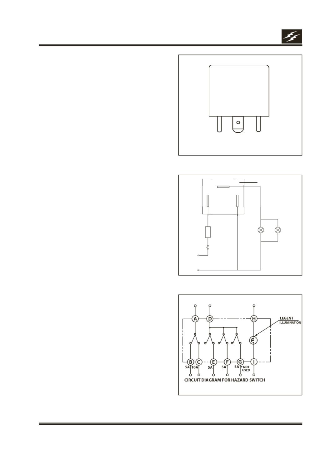
Fig. 47
Fig. 46
Fig. 48
+
FLASHER
5 A
Fuse
SWITCH
12 V
24 W x 2
-
B
E
L
17F. FLASHER UNIT :
Function
It provides blinking output to side indicators and
hazard warning lamps.
Location
It is located in cabin fuse box.
Connection details
Connection details are shown in Fig.46
Checking flasher unit
a) Connect bulb to the flasher unit and battery as
shown in Fig. 47. The bulb should blink at 90
±
30
cpm.
b) Disconnect one of 21 W bulbs. The remaining bulb
should blink atleast 1.8 times of (a) or 140 cpm
whichever is greater.
Please refer electrical circuits of Hazard warning & DI
flasher system.