


 1458 / 1526

ELECTRICALS
36
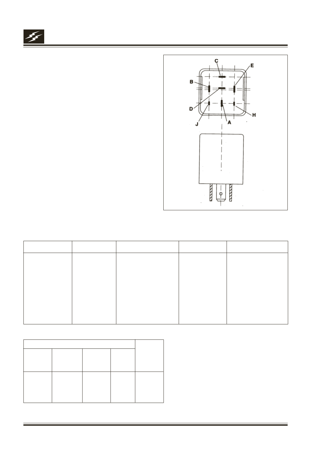
Fig. 43
Connection details
Terminal Name Pin Type
Description
Active Level
Condition
H
Input
Driver door switch
GND
Door Open
J
Input
Head Lamp Switch
VCC
Head Lamp on
D
Input
Seat Belt Switch
GND
Seat belt attached
C
Input
Ignition Switch
VCC
“Key in” Position
A
Output
Output from unit
VCC
See Perf. Check
B
Supply
Supply to unit
VCC
Permanent
E
Ground
Ground to unit
GND
Permanent
Performance check
Input
Output
Key in Driver
Head Seat
switch
door
lamp belt
switch switch switch
Active
Active
----
-----
Active
Inactive
Active
Active
-----
Active
Active
Inactive
-----
Inactive Active
17C. CHIME UNIT
(Fig. 43)
Function
It generates anoutput signal insome faulty condition
/ usage and passes it to the Buzzer Unit for various
abnormal conditions asmentionedbelow.
Seat belt open and key in ignition position.
Head lamps ‘ON’with key out and door open key in
anddoor open.
Location
Behind glove box on fire wall.
Output is Inactive in case of - After 10 +3 sec. of start
of chimingChange in Input condition rnakes output
Inactive.