


 1464 / 1526

ELECTRICALS
42
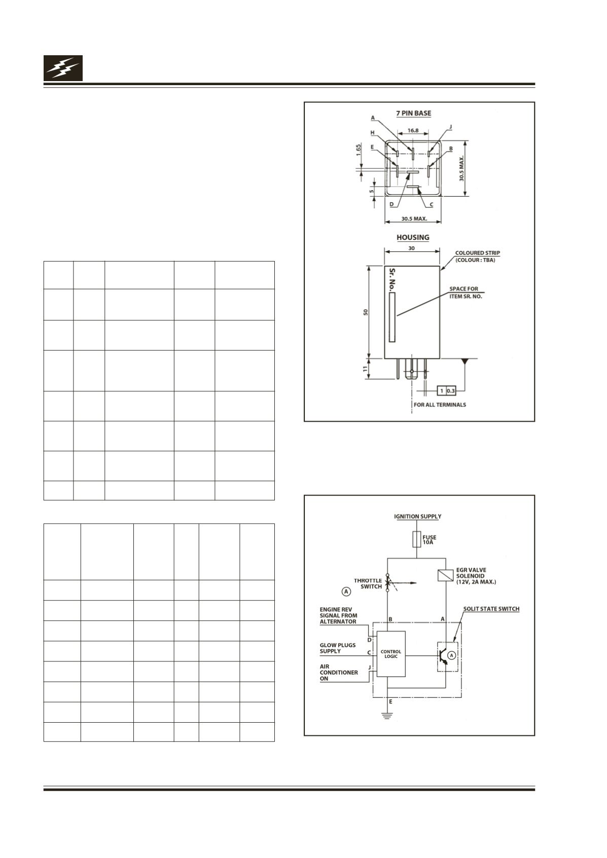
Fig. 52
Fig. 53
17H. EGR Controller (for 4DL TCIC) :
Function
It gets inputs from engine FIP throttle switch speed
signal through alternator, glow plug supply and AC.
The output is given to EGR solenoid switch which
further controls operation of EGR valve.
Location
It is located on the firewall inside the engine
compartment.
Table connection details :
TER.
TER.
DESCRIPTION ACTIVE CONDITION
NAME TYPE
LEVEL
E Ground Ground to
GND Permanent
point
C Input Glow plugs
VCC Glow plug
supply
ON
B Input Throttle switch VCC I/P till throttle
pedal reaches
set limit
A Output Output to EGR GND As per
Solenoid
Table 1
D Input Engine RPM Pulses As per
from alternator
Table 1
J Input Air conditioner VCC Air conditioner
supply
ON
H NC Not used
--
--
Performance Check :
IGEN THROTTLE GLOW AC ENGINE EGR
SUPPLY SWITCH PLUG ON REV.
VALVE
SUPPLY
FREQ.
SIGNAL
(H3)
--
TER. B TER. C TER.
TER. D TER. A
J
0
0
X
X
X Float
1
0
X
X
X Float
1
1
1
X
X
Off
1
1
0
0
X
On
1
1
0
1 <334 Off
1
1
0
1 >334 On
1=VCC, 0=GND / No supply / Float X=Don’t Care