


 1247 / 1526

ENGINE
79
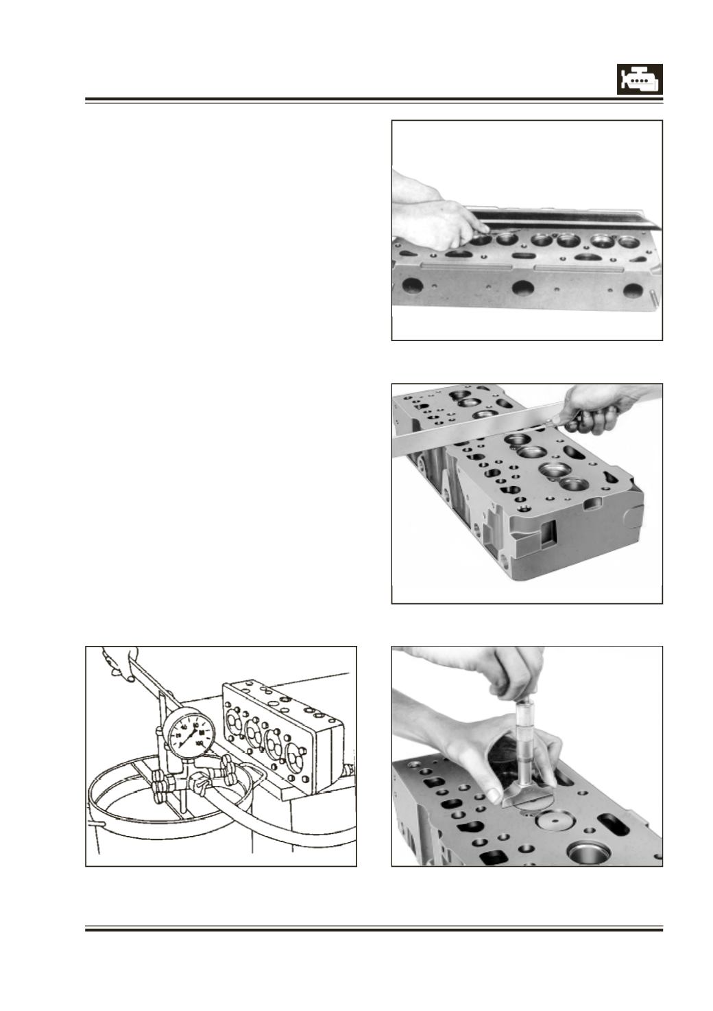
Fig. 8
Fig. 9
Fig. 10
Fig. 11
PRESSURE TESTING OF CYLINDER HEAD
1 Thoroughly de-grease, descale and clean cylinder
head.
2 Firmly screw on steel plate with rubber pads on
cylinder head. Block one outlet of upper cooling line
and connect water hose to other outlet.
3 Connect other end of water hose to a hand operated
water pump dipped in a container of hot water
preferably at 70 deg C to 80 deg C.
4 Test cylinder head for cracks/leakages with water
under a pressure of 5 bar. Fig. 8.
5 Alternatively, dip cylinder head along with sealing
plates in a tank containing water at 70 deg C to
80 deg C and connect hose to a compressed air
line. Pass compressed air at 5 bar and check
cylinder head for leakage/cracks.
6 Replace cylinder head having any cracks.
NOTE :
Do not remove the lower protective sleeve. If it is
removed for any other purpose install it back with new
sealing washer and apply recommended thread locker
and specified torque.
INSPECTION AND REPAIR
1 Check cylinder head surface with a straight edge
and feeler gauge, for unevenness (lengthwise and
crosswise). Fig 9 and 10.
2 If necessary, grind this surface just to clear the
unevenness. Ensure that specified machining
tolerance is not exceeded.
3 In addition to total cylinder head thickness
observe that the water jacket thickness at parting
surfaces must not be less than 6 mm.
4 After reconditioning of parting surfaces by
grinding, measure distance between valve head
and parting surface Fig. 11. Refinish valve seats, if
required.