


 1243 / 1526

ENGINE
75
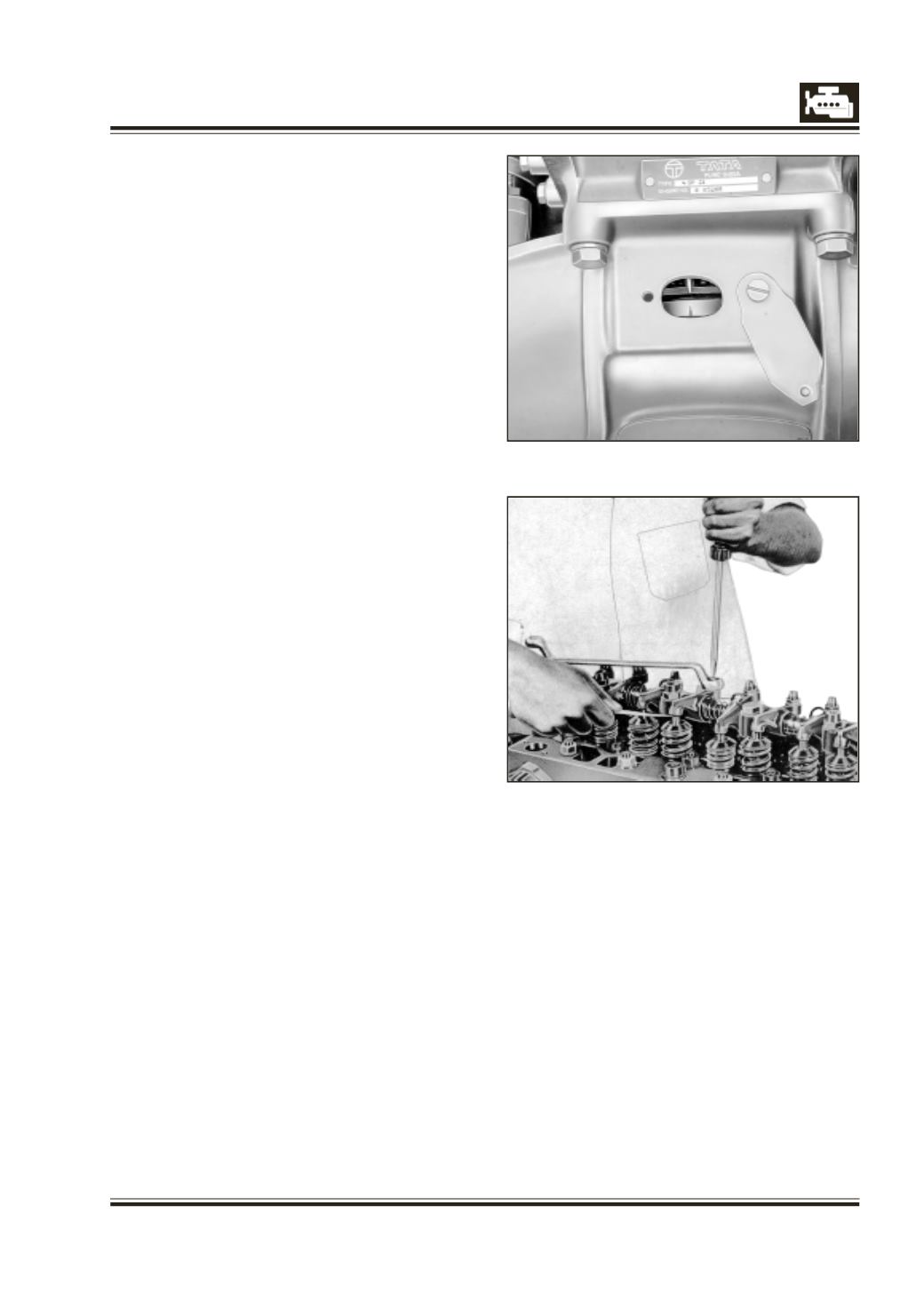
Fig. 1
Fig. 2
ADJUSTMENT OF VALVE CLEARANCE
(Cylinder head cover removed, Temperature: cold or
cooling system at maximum 50 deg C)
1 Adjust valve clearance in compression TDC and in
firing order of individual cylinders. Firing order is
1-3-4-2, beginning with first cylinder (starting at
radiator). Fig. 1.
Compression TDC is recognized by the
overlapping valves of counter-cylinder (counter-
cylinders are 1 and 4 or 2 and 3).
EXAMPLE
With valves of 4th cylinder in overlapping position,
valves of 1st cylinder can be adjusted or checked.
TURN ENGINE IN DIRECTION OF ROTATION ONLY.
2 For measuring and adjusting valve clearance, insert
pertinent feeler gauge between valve stem and
rocker arm.
Valve clearance is correctly adjusted, if feeler
gauge can be pulled through under slight
resistance.
3 If a correction of valve clearance is required,
loosen lock nut of ball-head screw. Adjust
clearance by applying screw driver to ball head
screw. Tighten lock nut. Adjust ball head screw in
such manner that feeler gauge can still be moved
smoothly with lock nut tightened again. Fig. 2.
4 Alternatively, valve clearance can be adjusted by
turning crankshaft only twice as follows:
a. Turn crankshaft to bring No. 1 piston at TDC
(compression stroke). To ensure this position
remove clutch housing inspection cover and turn
crankshaft to coincide TDC (red) marking on
flywheel/ring gear with pointer on crankcase.
b. Adjust valve clearance of valve numbers 1, 2, 3 and
5 starting from front end.
c. Turn crankshaft by 360 deg (in direction of
rotation) so as to bring piston No. 4 at TDC
(compression stroke).
d. Adjust valve clearance of valve numbers 1,2,3 and
5 starting from rear end (or 4, 6, 7 and 8 from front
end).
e. Refit clutch housing inspection cover, if removed.