


 1091 / 1526

51
GEAR BOX G-76
24. ASSEMBLYOF GEAR BOX
Place shifter fork assembly 1st / 2nd and Reverse/5th
over main shaft assembly at its proper place, keeping
notches towards coupling flanges side.
Place shifter fork 3rd/4th alone without shaft at its place
over main shaft sleeve such that its collar is facing
outwards.
Keep counter shaft assembly aligned with main shaft.
Insert two nos ball in holes of shifter shaft bore in
housing. Use grease for keeping them in position.
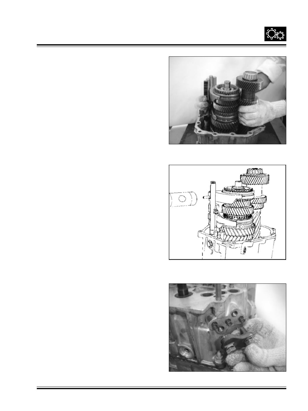
Hold and placemain shaft assembly along with counter
shaft assembly and shifter fork assembly in position
in the housing - Rear. Fig. 112
Fig. 112
Fig. 113
Fig. 114
While inserting shifter shafts in the housing,
ensure
that interlocking balls are not displaced.
Fit interlock pin - 12.8 mm length in shifter shaft 3rd/
4th. Insert shaft through the shifter fork. Align shaft
with hole of and fork then press spiral pin. Ref fig. 113
Place 3 Nos ball - 8 mm dia. and detent spring in
holes of housing. Detent spring is to lock 1st / 2nd
& 3rd /4th shifter shafts where as short and stiff
detent spring is to be used for Reverse/5th shifter
shaft. Fig. 114
Fix gasket to detent cover and tighten hex screws
along with spring washer. Fit rollers 4 Nos over pins of
selector shaft.
Slide shifter shaft - Reverse speed in the housing bore.
Locate selector & shifter finger between shifter dog -
3rd/4th notch and reverse speed shifter shaft under
cut.