


 1086 / 1526

46
GEAR BOX G-76
Assemble the gear box without compression spring (4) and without Front Cover.
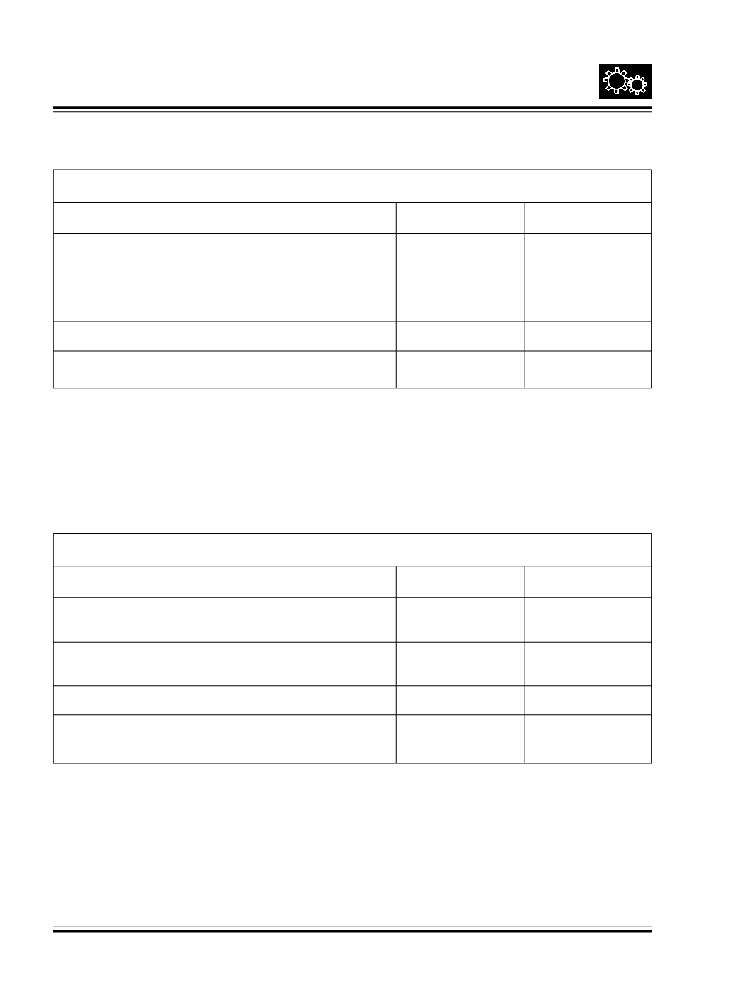
4.0 Dimensions to be measured
Symbol
Example
4.1 Measure the Front Cover depth along with the
P
5.75
gasket Fig. 97 and 99
4.2 Measure drive shaft bearing projection over
Q
5.50
housing face Fig. 100
4.3 Difference P-Q
R
0.25
4.4 Shims required (Maintain end play of 0.07 to 0.1 mm)
S
0.15
DRIVE SHAFT SHIM SELECTIONAT FRONT COVER
Fit Front Cover with shims ‘S’ and check axial play at coupling flange. The play must be with in 0.07 to 0.10 mm.
Change shims if required, to get required play. Remove Front half and re-assemble compression spring.
COUNTER SHAFT SHIMSELECTIONAT FRONT COVER
Assemble the gear box without compression spring and without Front Cover
5.0 Dimensions to be measured
SymboI
Example
5.1 Measure Front Cover depth along with the gasket
T
4.75
Fig. 99 and 100
5.2 Measure counter shaft bearing projection over housing
U
4.50
face Fig. 105
5.3 Difference T-U
V
0.25
5.4 Shims required (Maintain pre-load of 0.03 to 0.06 mm)
W
0.30
V+0.05
Fit compression spring and Front cover with shims ‘W’ and check for free rotation.
Slide roller ring along with R.I. gear over shaft.
Fit another snap ring