


 108 / 1526

69
4 DLT ENGINE
E
nsure that cylinder head locating hollow dowel is in
position on crank case.
E
nsure that timing pin 2654 5890 03 09 is installed in
position.
I
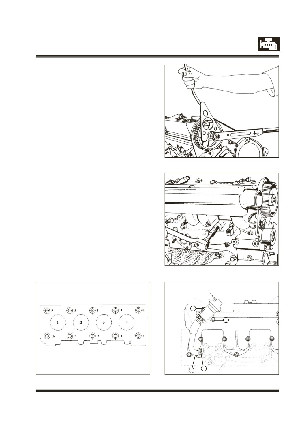
nstall cylinder head and tighten cylinder head
mounting screws to 5 mkg torque in the correct
sequence i.e. from centre to outwards.Then retighten
screws to 7 mkg torque in the same sequence.
T
hen tighten to 10.5 mkg torque. Refer Figure 136
F
it belt tensioner locking screw and timing gear train
rear cover mounting screw at cylinder head.
I
nstall wood ruff key, cam shaft gear and spacer.
T
ighten cam shaft gear mounting screw to specified
torque use spl. tool 2654 5890 05 01. Refer
Figure 137
Fit
- Inlet manifold.
- Exhaust manifold. Refer Figure 138
- EGR vlave assy. (if fitted) Figure 139
Fig. 137
Fig. 138
Fig. 139
Fig. 136
4
3
1 2
Vacuum Hose from
Solenoid Valve
EGR Valve
EGR Tube