


 107 / 1526

68
4 DLT ENGINE
I
nstall both wood ruff keys in position on crankshaft
front and slightly tap crankshaft gear and push it over
crankshaft.
I
nstall crankshaft pulley in position.
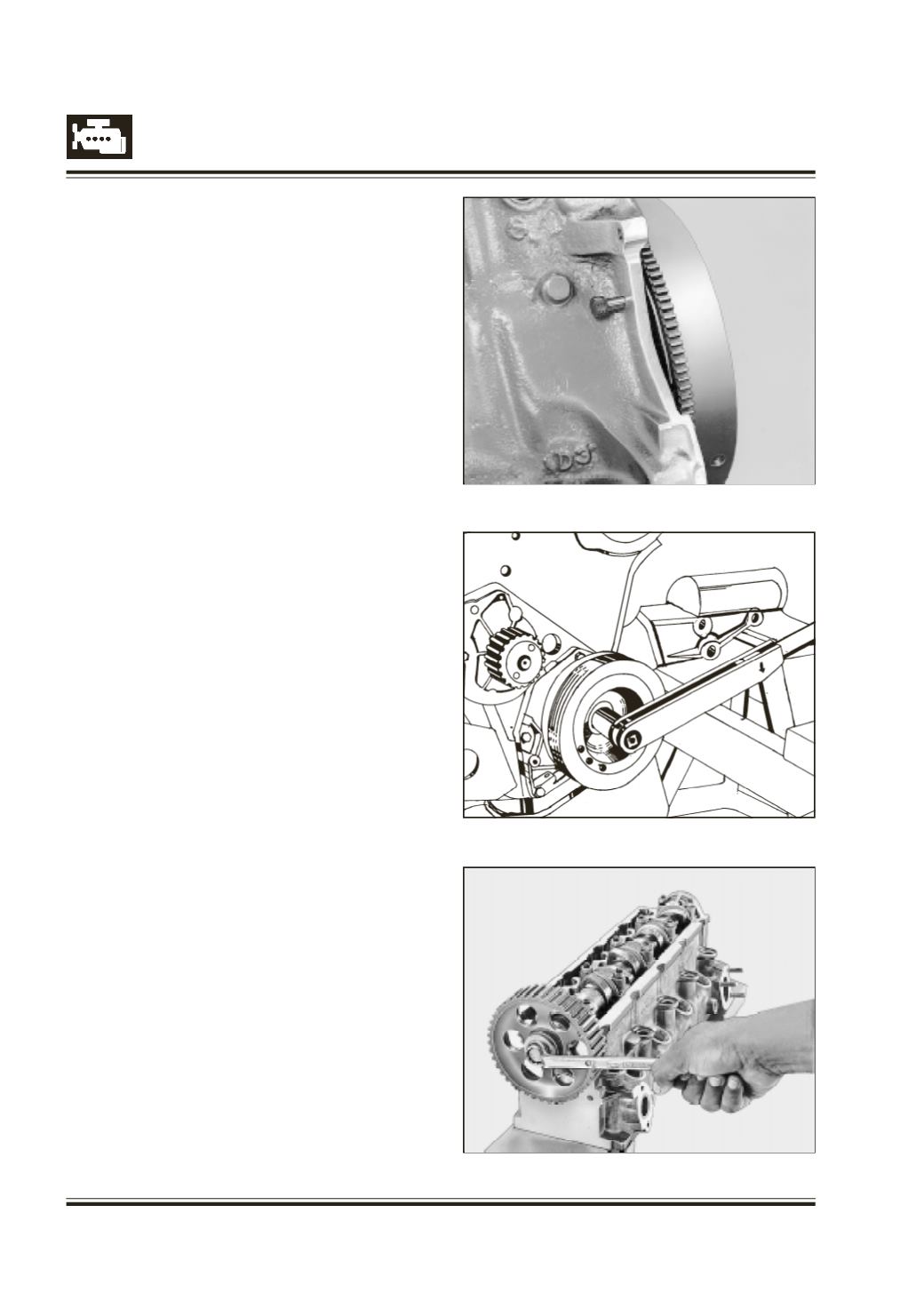
L
ock fly wheel with timing pin, 2654 5890 03 09. Refer
Figure 133
S
crew in crankshaft pulley mounting bolt with spacer
and tighten it to specified torque. Refer Figure 134
M
easure piston projection above crank case and select
correct thickness of cylinder head gasket.
Refer repair data.
R
otate cam shaft and bring valves of 1st cylinder to
compression TDC position. Refer Figure 135
Fig. 133
Fig. 134
Fig. 135