


 114 / 1526

75
4 DLT ENGINE
T
ighten adapter cap nut.
R
otate crankshaft in anti-clockwise direction by
approximately 30 degrees.
P
recisely locate bottom dead center of fuel injection
pump plunger by slight rotation of crank shaft in
either direction.
S
et dial gauge reading to 0.
R
otate the crank shaft clockwise to TDC position
and insert the timing pin in the flywheel. Refer Figure
156
S
lowly rotate fuel injection pump till plunger lifts by
0.71
+0.02
mm (dial gauge). Rotating fuel injection pump
towards crank case increases plunger lift and vice
versa. Refer Figure 157
F
ully tighten fuel injection pump front mounting nuts,
rear mounting bolt and taper nut in this position.
R
emove timing pin from cylinder block.
Rechecking timing
R
otate crank shaft by two full rotations. Check
injection pump plunger lift is 0.71
+0.02
mm (dial gauge).
I
n this position it should be possible to insert timing
pin in the flywheel. If not, repeat fuel injection timing
adjustment procedure.
R
emove dial gauge and timing adapter, 2654 5890
05 09. Refer Figure 158
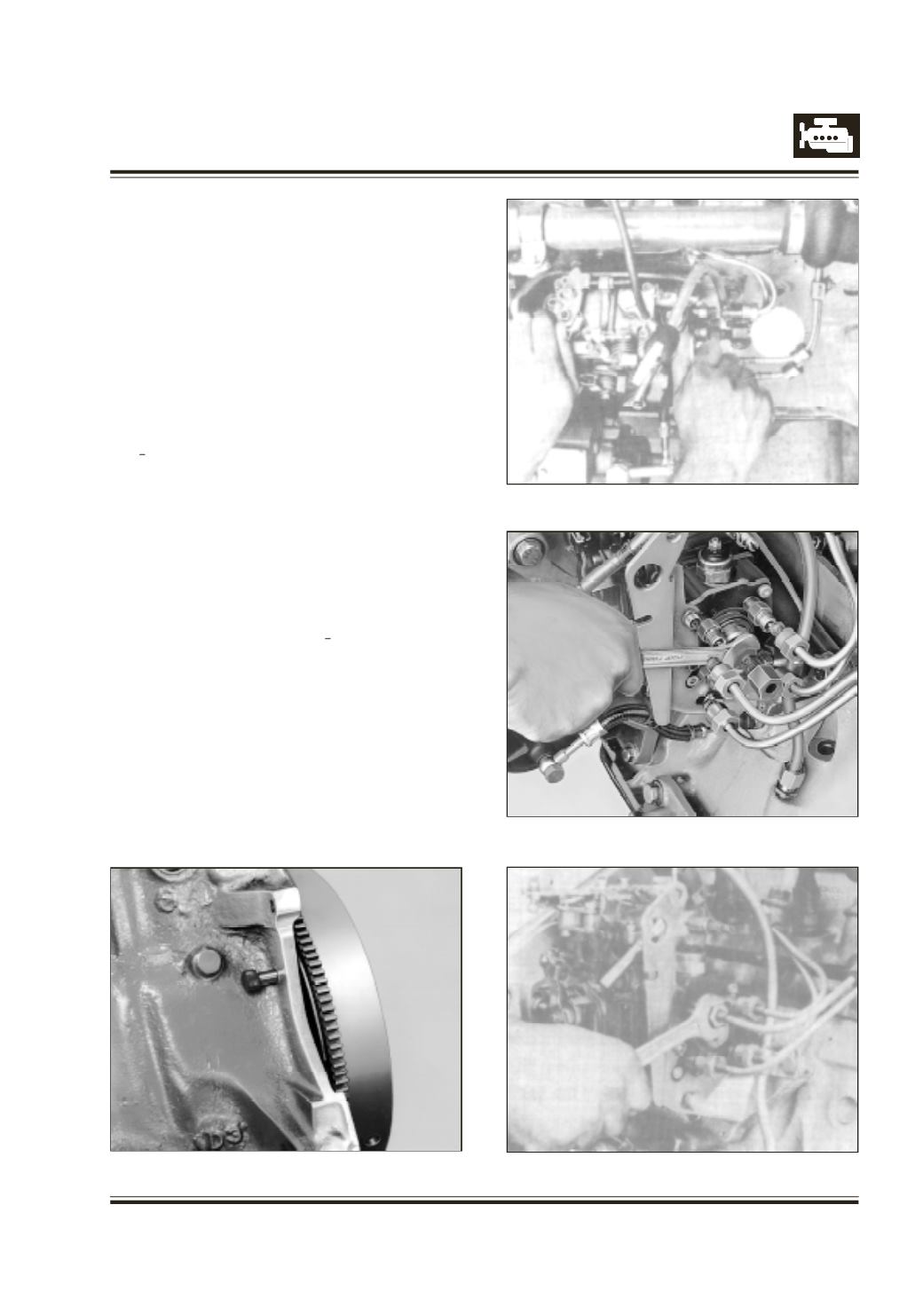
F
it back timing plug on fuel injection pump.
C
onnect high pressure injection pipes to fuel injection
pump. Refer Figure 159
Fig. 157
Fig. 158
Fig. 159
Fig. 156