


 104 / 1526

65
4 DLT ENGINE
I
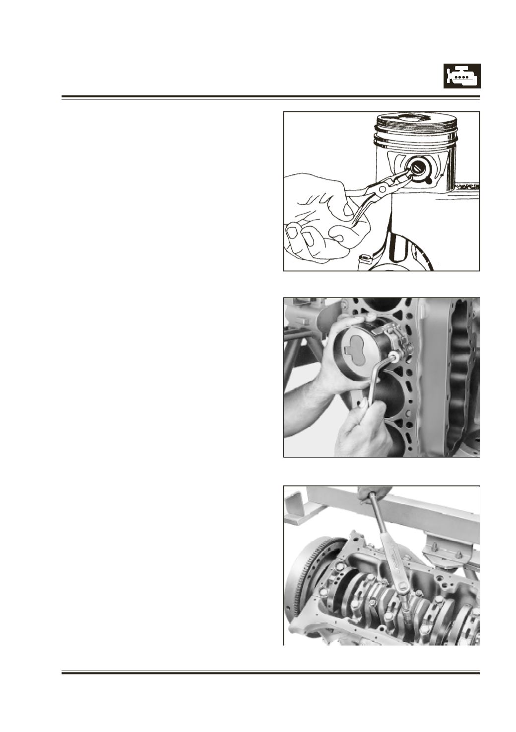
nsert piston pin. Fit piston pin spring clip
Refer Figure 123
A
pply oil on piston, piston rings, cylinder bore and
bearing shells.
T
urn crank shaft and bring crank pin journal to top
most position onto which connecting rod with piston
is to be fitted.
I
nsert connecting rod with piston upto piston rings
into cylinder bore with arrow on piston crown pointing
towards front. Clamp piston ring compressor over
piston rings such that piston with piston rings can
slide inside it. Refer Figure 124
P
ush piston gradually inside cylinder bore using
wooden handle of mallet till connecting rod locates
on crank pin journal. Slowly rotate crank shaft,
simultaneously pushing piston till crank pin journal
reaches BDC position.
I
nstall connecting rod bearing cap with bearing shell
on connecting rod ensuring that bearing shell lugs
are on same side.
T
ighten connecting rod bearing cap mounting nuts
to specified torque. Refer Figure 125.
Fig. 123
Fig. 124
Fig.125