


 111 / 1526

72
4 DLT ENGINE
R
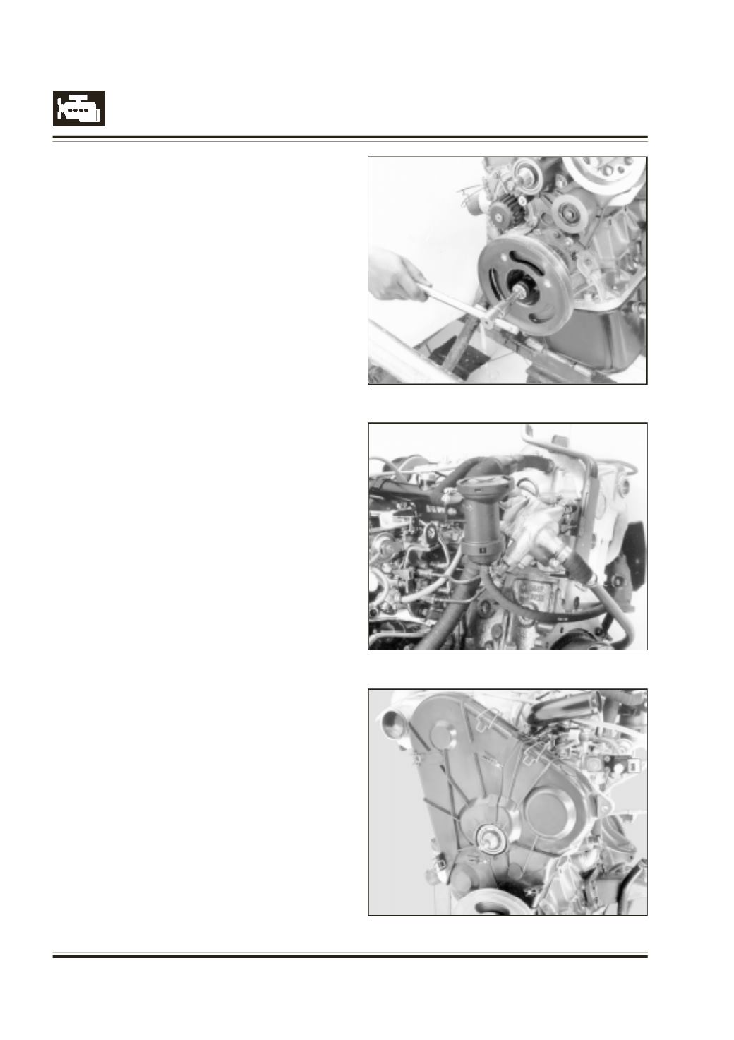
emove timing bolts and timing pin
R
otate crank shaft with spanner 2654 5890 03 02
by full two turns in direction of engine rotation.
Refer Figure 146
T
ry fitting timing bolts and timing pin in its position.
If it is not possible to fit any one, repeat timing belt
installation procedure from beginning.
ENSURE THAT TIMING BOLTS AND TIMING PIN
ARE REMOVED AFTER TIMING BELT FITMENT.
- FIP timing adjustment procedure is given
separately. Connect engine stop solenoid and cold
start advance unit electrical cable to fuel injection
pump
Fit
- Thermostat assy Refer Figure 147
- Oil separator and hoses
- FICD unit
- Fuel return pipe from FIP to fuel tank
- High pressure injection pipe from injectors to FIP
- Coolant pipe
- Over flow hose from 1st injector to fuel injection
pump
I
nstall all three (front left, front right and front lower)
timing gear train covers.
L
ock front timing cover with clip and toggle clamps.
Refer Figure 148
Fig. 146
Fig. 147
Fig. 148