


 102 / 1526

63
4 DLT ENGINE
ENGINE ASSEMBLY PROCEDURE
F
it piston Cooling nozzles.
F
it drive shaft spigot bearing and oil pump drive
sprocket gear on crankshaft using suitable drift.
I
nstall thrust washers in crankcase at their respective
location on 4th Main bearing sides.
A
pply light coat of engine oil to main bearing shells
and main journals.
I
nstall crank shaft.
I
nstall thrust washer on 4th main bearing cap sides.
I
nstall 4th main bearing cap with shells and thrust
washer in its position on crank case.
I
nstall 1st, 2nd and 3rd main bearing caps with shells
in their respective position on crank case.
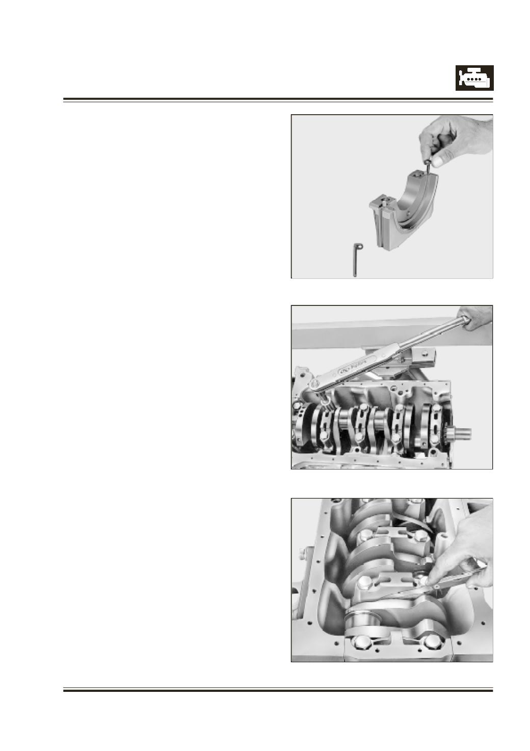
C
lean the grooves of 5th main bearing cap and make
it free from oil and grease.
A
pply a thin layer of maxifix adhesive-S758 (Dunlop
make) in the groove and allow it to dry for 10 minutes.
A
ssemble both the side seals on 5th main bearing
cap - Refer Figure 116 avoiding air bubbles and press
firmly. Cut off the extra length of side seal keeping 2
mm projection above cap height.
A
pply ANABOND 611 between mating faces of 5th
main bearing cap and cylinder block.
I
nstall 5th main bearing cap with shell and side seal
in its position on crank case.
W
hile installing ensure that
- Side seals are not getting cut or dislodged from its
position on 5th main bearing cap.
- Thrust washers are not dislodged from their seat
in crank case and 4th main bearing cap.
- Bearing shell lugs are on same side.
T
ighten main bearing cap mounting bolts evenly and
uniformly to specified torque. (First 3rd cap, next 4th
and 2nd, lastly 5th and 1st) Refer Figure 117
C
heck that end float of crank shaft is within specified
limits. Refer Figure 118
Fig. 116
Fig. 117
Fig. 118