


 97 / 1526

58
4 DLT ENGINE
4. Heat the vessel and measure the water
temperature with proper thermometer.
5. Note down the temperature when dial gauge
needles starts moving indicating valve opening.
6. Theopening temperatureand fully open temperature
measured should be as mentioned in repair data.
I
f they do not meet the specifications, replace the
thermostat element.
INSPECTION OF TIMING BELT
C
heck belt in detail. If following flaws are evident,
replace belt with new one.
- B
ack surface glossy, non elastic and so hard that
even if finger nail is forced into it, no mark is
produced.
- C
racked back surface rubber
- C
racked or exfoliated canvas
- C
racked tooth bottom
- S
ide of belt cracked
- S
ide of belt badly worn
- B
adly worn teeth
- M
issing tooth
I
t is advisable to replace belt while reconditioning the
engine.
NOTE:
N
ormal belt should have clear cut sides, as if cut with
a sharp knife.
In initial stage of wear, load side tooth flank will look
like fluffy canvas fiber, rubber gone and colour changed
to white.
I
n last stage of wear, canvas on load side tooth flank
will be totally worn out exposing rubber.
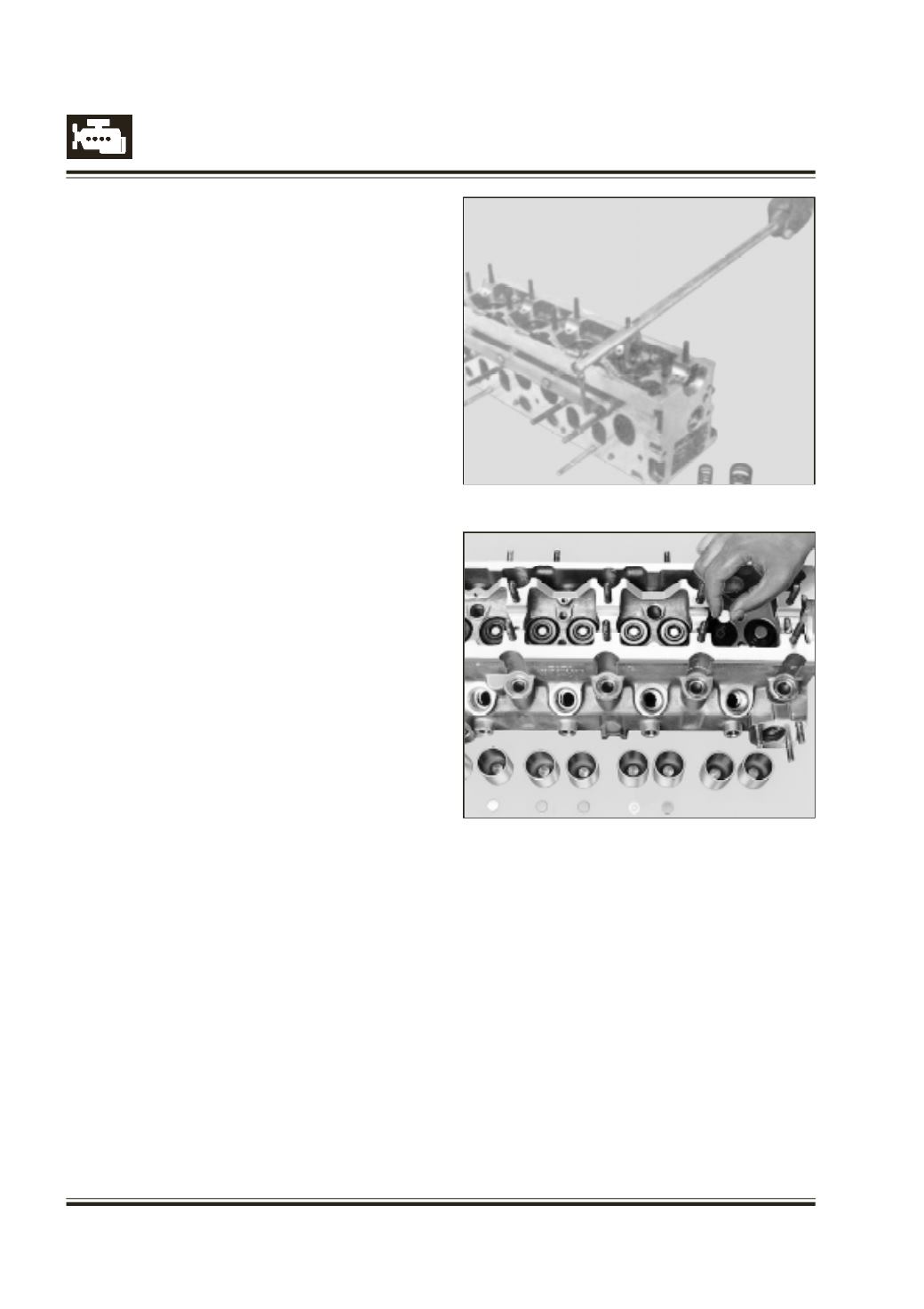
ASSEMBLY OF CYLINDER HEAD
I
nstall valves in their respective positions.
I
nstall spring seat, valve spring and valve retainers.
Fig. 103
Fig. 104
F
it support rail, 2654 5890 05 06 on cylinder head.
W
ith spring compressor, 2654 5890 05 07 compress
valve spring and install valve lock halves.
Refer Figure 103
IN CASE OF ANY REPLACEMENT OF TAPPET/
VALVES OR MACHINING OF VALVE SEAT USE
THINNEST SIZE OF SHIMS.
I
nstall original or thinnest size shims in their respective
positions. Refer Figure 104
A
pply light coat of moly paste grease over shims.
Smear tappet outside diameter with engine oil.