


 225 / 310

ENGINE
179
REMOVAL
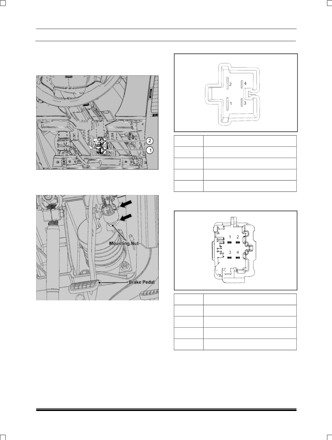
1. Disconnect electrical connections of brake light
switch (1) and brake switch for cruise control (2)
(If fitted)
.
2. Loosen the mounting nut of brake switch and take
out the brake switch by rotating anticlockwise di-
rection.
INSPECTION
Disconnect the connector and check the continuity
between the following pins. When the pedal is de-
pressed there should be connectivity and when it is
released to rest position there should not be connec-
tivity.
Brake Light Switch:
Pins 1 and 2 for Brake light circuit.
Pins 3 and 4 for Brake signal to EMS circuit
Brake switch for Cruise
Pins 1 and 3 for Brake pedal signal for cruise control.
For switch adjustment details, refer brake section
.
PIN OUT
PIN NO DESCRIPTION
1
Ignition
2
Supply to tail lamp
3
Ignition
4
Signal to EMS
BRAKE PEDAL SWITCH
(FOR VEHICLES WITH
CRUISE CONTROL)
PIN NO DESCRIPTION
1
Ignition
2
NC
3
Signal to EMS
(Cruise Control)
4
NC
REFITMENT
1. Fit the brake light switch on the mounting bracket
and tighten its mounting nut.
NOTE
Refer brake section for brake switch adjustment de-
tails.