


 211 / 310

ENGINE
165
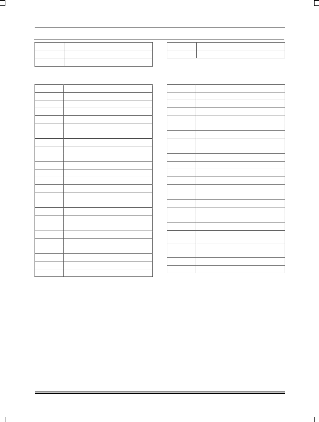
PIN NO
DESCRIPTION
A92
Throttle valve DC motor +ve output
A93
Throttle valve DC motor -ve output
PIN NO
DESCRIPTION
A94-A96 Spare
58 PIN CONNECTOR PIN DETAILS
PIN NO
DESCRIPTION
B1
Power supply #1
B2
Power ground #1
B3
Power supply #3 (
actuators
)
B4
Power ground #2
B5
Power supply #2
B6
Power ground #3(
actuators
)
B7
Spare
B8
A/C trinary sensor input
B9
Crise control demand input
B10
Spare
B11-B12 NC
B13
Accelerator pedal 2, input
B14
Accelerator pedal 2, return
B15-B16 Spare
B17
Clutch switch 90%
B18
Clutch switch 10%
B19
Key switch input
B20-B23 Spare
B24
Accelerator pedal 1, Supply
B25
Accelerator pedal 1, input
B26
Accelerator pedal 1, return
B27- B28 Spare
B29
Accelerator pedal 2, supply
B30
Brake redundant return
PIN NO
DESCRIPTION
B31
NC
B32
Brake main switch
B33
Spare
B34
Cruise control demand return
B35- B36 Spare
B37
Fan low speed output
B38
Spare
B39
LIN return
B40-B43 Spare
B44
NC
B45
Main power relay output
B46
Spare
B47
Vehicle CAN low signal
B48
Vehicle CAN high signal
B49
Fan high speed output
B50
Spare
B51
A/C relay out
B52
LIN
B53
Development CAN high signal (devel-
opment only)
B54
Development CAN low signal (devel-
opment only)
B55
MI lamp output
B56-B58 Spare