


 199 / 310

ENGINE
153
SYSTEM FLOW
For system flow schematic refer air intake system
schematic layout.
The exhaust gases are made to pass through the
turbine which will rotate the compressor mounted on
the same shaft on the air inlet side. The air from the
air filter is sucked by compressor. The compressed
air then flows through an intercooler and then to the
intake manifold. For more information refer Air intake
system.
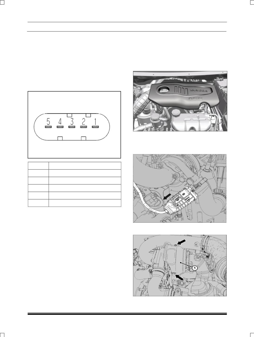
PIN OUT
PIN OUT FUNCTION
1
POWER
2
GROUND
3
C.A.N HIGH
4
PWM (OPTIONAL)
5
C.A.N LOW
2.1.8.3.2 MAINTENANCE
2.1.8.3.2.1 ON VEHICLE REPAIRS
A. TURBOCHARGER
REMOVAL
1. Disconnect the battery connection.
2. Pull out the Engine cover.
3. Remove the Air Filter assembly.
(Refer air filter
removal procedure).
4. Disconnect the electrical connection of the turbo-
charger.
5. Remove the Turbocharger heat shield
(1)
by re-
moving the two mounting bolts.