


 198 / 310

ENGINE
152
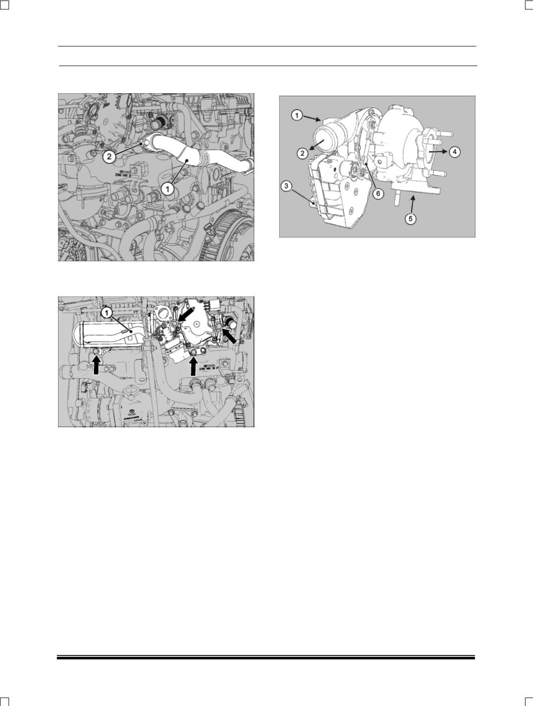
8. Loosen and remove the hex flange bolts
(2)
to
disconnect the EGR pipe
(1)
from EGR cooler.
9. Loosen and remove the hex flange bolts to dis-
connect the EGR cooler module
(1)
mounted on
the intake manifold.
FITMENT
For fitment follow reverse procedure of removal.
NOTE
Use new gasket every time and tighten bolts to spec-
ified torque.
2.1.8.3 TURBOCHARGER
2.1.8.3.1 DESCRIPTION
1. Compressor Inlet
2. Compressor Outlet
3. Electric connection
4. Turbine outlet
5. Turbine inlet
6. Actuator rod assembly
Compared to traditional turbochargers an electroni-
cally controlled Turbocharger has better performance
at low engine speeds. The turbocharger is controlled
by the EMS and the EMS ECU monitors the turbo-
charger to provide optimum boost.
FUNCTION
The actuator rod assembly in the turbine housing
controls the turbocharger vanes which help in getting
optimum boost. At low engine speeds when exhaust
flow is low, the turbocharger vanes are positioned
with minimum opening by the actuator. This increas-
es the velocity / pressure of the exhaust gases
pushing against the turbine blades, making the tur-
bine spin faster and generating more boost. As
engine speed increases, so does the exhaust flow,
the turbocharger vanes are opened to reduce turbine
pressure and maintain the target boost.
ADVANTAGES / FEATURES
•
Good low end torque.
•
Good transient response.
•
Good fuel economy.
•
Increased useful engine operating range.
•
It provides more matching level of pressure boost
even to a slow spinning turbine without providing
too much of a boost at higher speed.
•
Low engine noise.
•
Lower emission.