


 1002 / 1428

TRANSAXLE
141
14. POWER UNIT (PWU) BASE PLATE
REMOVAL AND RE-FITMENT ON BENCH:-
Removal:
CAUTION
Ensure there is ‘NO PRESSURE’ in the
hydraulic circuit.
1. Disconnect all the connectors of the system
wiring harness (DC Motor, Cultch Position
Sensor and Transmission Control Unit) and
remove the ‘Plastic Clip’ pulling it out from its
threaded hole on the ‘Power Unit Base Plate’
body.
2. Remove the ‘Mechatronic Gear Actuator’ unit
(MGA) first (refer the procedure 7.
Mechatronic Gear Actuator Unit (MGA)
Removal and Re-Fitment on Bench).
Installation:
1. Assemble the new ‘Power Unit Base Plate’ on
the fixture.
2. In order to guarantee right ‘Mechatronic Gear
Actuator’ translation during the mounting, to
avoid O-rings damages, screw ‘Special tool –
guide rods’ φ6x100 mm length, with 15 mm
threaded M6, in the ‘Power Unit Base Plate’
holes used by ‘Mechatronic Gear Actuator’
fixing screws.
3. Assemble the new O-rings on the new
connectors.
4. Mount the new connectors with O-rings in
their seats on new ‘Power Unit Base Plate’,
after lubrication with new ‘CS Speed’ oil also
lubricate the ‘Mechatronic Gear Actuator’
seats.
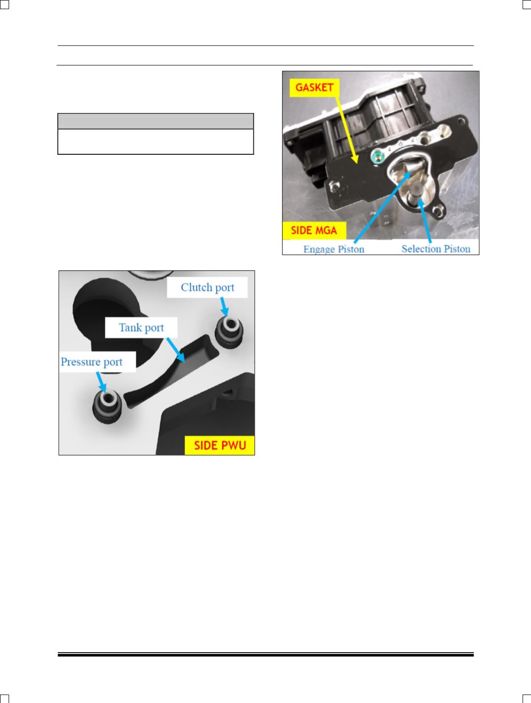
5. Remove traces of oil from the ‘Mechatronic
Gear Actuator’ seal surface in contact with
gasket with care to avoid contamination from
foreign materials (dust, metal burrs, etc…) or
surface damages.
6. Assemble the new gasket on the ‘Mechatronic
Gear Actuator’ with the correct orientation,
inserting the centering pins into the fixing
holes of the ‘Mechatronic Gear Actuator’
body.
7. Position the ‘Mechatronic Gear Actuator’ with
gasket over the ‘Power Unit Base Plate’ using
the ‘Special tool – guide rods’ for reference
and moving it parallel towards the mating
surface.