


 864 / 1575

ELECTRICAL
44
8.4.4 HEAD LAMP
HEAD LAMP BEAM ADJUSMENT
This system consists of the headlamp leveling switch and headlamp leveling motor. It is used to lower both
headlight low beam aiming angles from the initial setting level by operating the leveling switch on the master
light switch. The head light must be properly aimed in order to maintain maximum road safety as regards
proper road illumination and to reduce the glare on the on coming traffic. It is recommended to check the
aiming of head lamps periodically and whenever bulbs are replaced.
NOTE:
When inspecting and adjusting the headlight beam, make sure to set the leveling switch to the
"0"
position
with the ignition switch "ON".
Before adjusting the headlamp beam:
1. The tyre pressure should be as specified and the car should be on level ground.
2. Vehicle should be in unladen condition (
only driver, spare wheel and STD accessories
).
3. Vehicle should be rolled for a few meters after loading to allow the suspension springs to settle.
4. The headlamp should be set one at a time by either putting OFF the opposite side lamp or masking.
5. Use suitable screw driver of required length to reach the toothed wheel adjustment.
6. The head lamp leveling switch should be in “zero” position.
Procedure for aiming and leveling setting of headlamps low beam for LH traffic:
1.Dimension, Arrow, lines and values should not appear on the screen.
2.Screen colour should be light and non-reflecting and marking lines should be dark and 5 mm thick with
sharp features.
3.The screen details are shown for RHD vehicle headlamp setting .Headlamp setting for LH vehicle will be
mirror opposite.
4.The setting to be checked with the vehicle against the screen. Adjust the focusing (
Horizontal
movement
) and leveling (
Vertical movement
) only if required to aim the lamp low beam pattern against
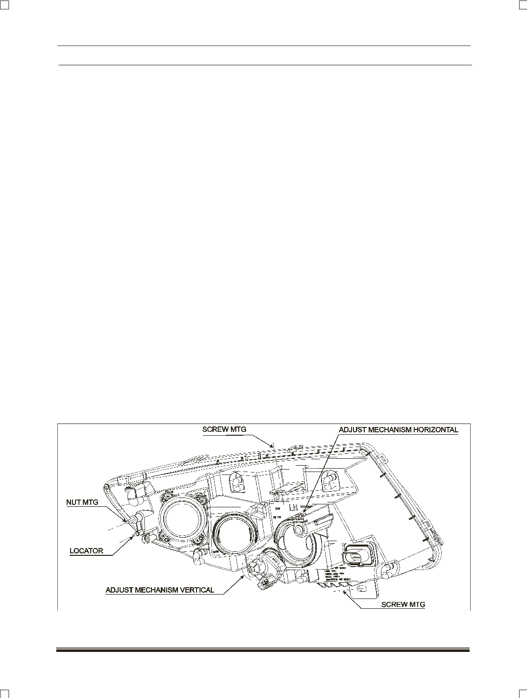
the dividing line on the board for respective headlamps (
LH and RH
). Refer lamp view for location and
direction of screw driver / Allen key (H6) rotation with respect to movement of adjustment.