


 672 / 1575

BRAKES
18
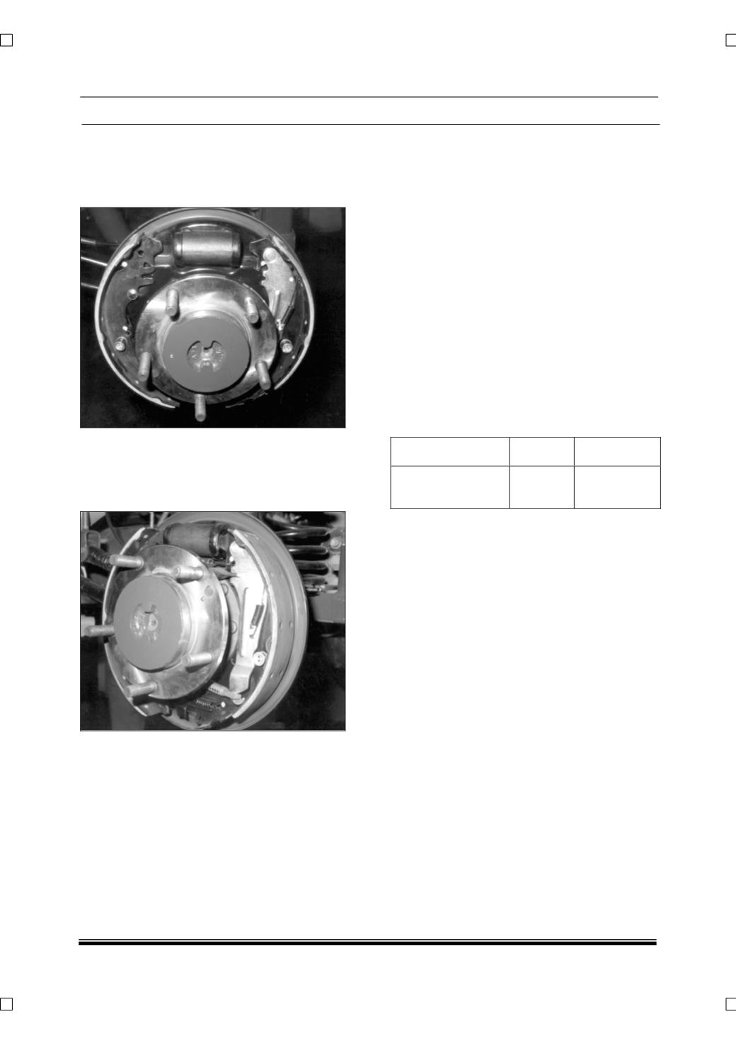
Ensure shoe-sliding platforms on the back plate
(1) are smooth and not corroded. If necessary,
Clean the filings and apply a light smear of
Graphite grease (high melting point grease) to
each platform.
Examine the adjuster assembly to see it is in good
working order and ensure the adjuster nut is free
to run the full length of the thread. Care must be
taken to fit left and right hand thread nuts
properly.
FITTING SHOES
ASSEMBLING
Lightly smear the following parts with special
grease as given. Keep the grease away from the
shoe linings and all hydraulic parts.
1. Tips of new shoes - High melting point grease.
2. Hand brake strut slots - Graphite grease.
3. Adjuster Pushrod Threads - Mineral oil base
grease.
Note:
When new shoe is fitted, ensure to fit new
shoe return springs also. Always fit new shoes in
pairs to both the sides of the vehicle. (RLH and
RRH sides)
Do not polish lining with sand paper or emery
paper. If lining is polished with sand paper or
emery paper, hard particles of sand paper will be
deposited in the lining resulting in damage of
drum surface.
Brake Lining
Standard Service Limit
Lining Thickness
above the rim
5.4 mm
1.0 mm
Refer to the illustration. Assemble Male (12)and
Female (9) pushrods (to its Min. length) with
adjuster nut (11) along with thermo clip (10),
taking care of the thermo clip position as shown in
the illustration (Ensure to fit the thermo clip facing
wheel cylinder for satisfactory functioning of the
auto adjuster mechanism).
Assemble the abutment end spring (8) between
the shoes. Place the shoes, springs along with
adjuster in position on to the platforms of the back
plate and locate the spring (8) below the riveted
abutment plate and the shoes in the abutment
groove. Hook the shoe return spring (7) (short
length coil) to the leading shoe, with the adjuster
assembly in its minimum length condition,
assemble the adjuster assembly between the
shoe webs. Attach the other end of the shoe
return spring (7) to the opposite end of the Trailing
shoe (3).Adjust the length of the adjuster until the
shoes will clear the wheel cylinder pistons.
Fit the pawl lever (18) to the spring dowel (20, 21,
22)inserting one leg of the pawl between male
push rod end and shoe web of the leading shoe
and the other end of the pawl leg resting on the
adjuster nut (11).Hook the short end of the spring
(19) into the hole in the pawl lever (18) and use
pliers to attach the opposite end of the spring on
to the shoe web (2).