


 288 / 745

6F33 TRANSAXLE
20
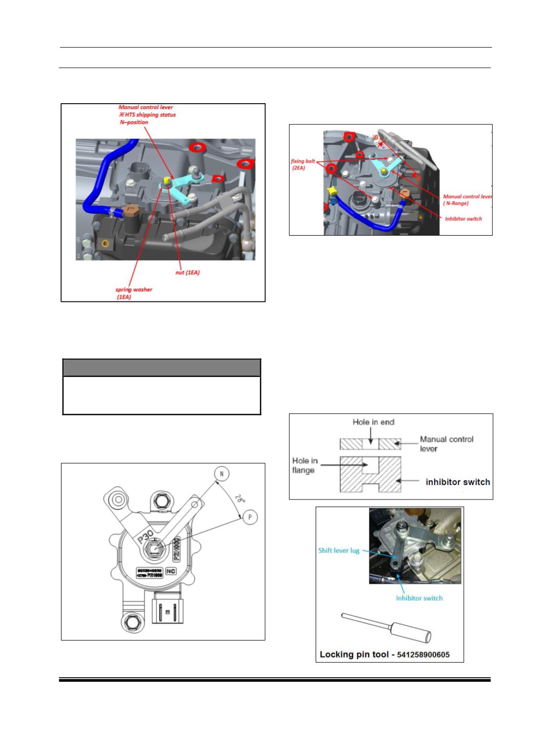
C. REMOVAL MANUAL CONTROL LEVER
(BASED ON SHIPPING CONDITION)
1. Rotate the manual control lever smoothly to N-
Range
2. Remove (1) nut, (2) spring washer (3) manual
control lever smoothly.
CAUTION
Never reuse (1) spring washer (2) nut.
Scrap the manual control lever.
REFERENCE VIEW
Manual control lever position for A/T shipping
condition (N-Range)
D. ADJUSTMENT METHOD OF INHIBITOR
SWITCH
(Manual Control Lever ‘N’-Range Setting
Method)
1. From method of install inhibitor switch, After
installation of manual control lever.
2. Set the manual control lever to the ‘N’-range.
3. Loosen the inhibitor switch fixing bolts and turn
the inhibitor switch body so the hole in the end
of the manual control lever and the hole (section
B-B in the figure) in the flange of the inhibitor
switch are aligned.
4. Put the position locking pin into the hole
between manual control lever and inhibitor
witch.
5. Tighten the bolts for inhibitor switch 10 ~ 12 Nm
torque. (Condition of locking pin insertion on ‘N’-
range.) Make sure that the position of the
inhibitor switch does not move at this time.