


 865 / 1119

ELECTRICAL
52
14.3
COMBI
STALK
REPLACEMENT
PROCEDURE
1. Remove the combi switch from vehicle. Refer
removal & refitment of steering nacelle from
steering section.
2. Disconnect combi switch connection.
3. Remove the two mounting screw of the stalks
as shown below
4. As shown, Two screws are dismantled to remove
light stalk. Same two screws on wiper side to be
removed to dismantle wiper stalk
5. Remove the stalk.
INSTALLATION:
1. Fit the new stalk.
2. Tight the mounting screws of stalk.
3. Fit the combi switch.
Torque value Table
Component
Tightening
torque value
Light / Wiper Stalk tightening
torque in Daesung make
Combi Switch
0.3 to 0.4 Nm
Light / Wiper Stalk tightening
torque in MRPL make Combi
Switch
6 to 8 kgf-cm
Clock Spring
1.2Nm
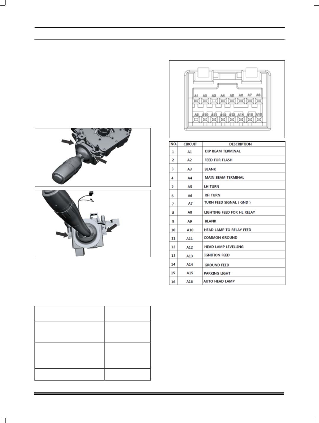
14.4 PINOUT DETAILS:
a) Light Stalk connector