


 643 / 1119

SUSPENSION
29
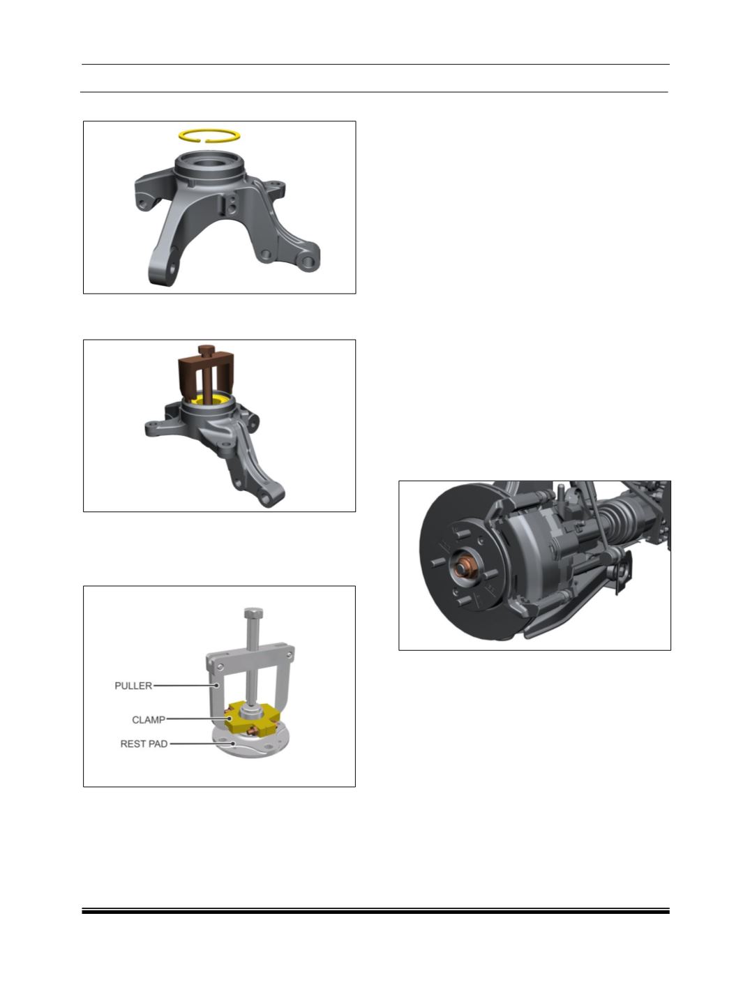
16.Remove Circlip from Knuckle.
17.Pull out Knuckle bearing using puller part No.
2779 5890 3302.
18.Using clamp part No. 2779 5890 3303 puller
part No. 2654 5890 3508 and rest part No. 2702
5890 2612 remove inner race of bearing from
the hub.
ASSEMBLY:
NOTE:
Before Installation refer S
ub assembly of knuckle /
Hub & Bearing installation procedure.
1. Follow the above steps in reverse order in
appropriate sequence for its assembly.
NOTE:
High / Low point matching on Hub and Disc
Observe the condition of disc surface. If the disc
surface is smooth ensure that punch mark (Low
Point) on disc and hub (High Point) are aligned and
assembled.
If the disc surface is uneven showing rough marks,
grooves - machine it to the specified limit; measure
the run out on dia. 220 w.r.t. hub and disc resting
face.
Punch mark around bolt hole where run out on dia.
220 is at low point.
Align low point on disc and high point on hub while
assembly. Assemble with countersunk screws.
2. Tighten drive shaft nut 24.5 ± 1.5 kg-m torque
and lock by staking.
3. Ensure that oil seal in transaxle is not damaged
while fitting drive shaft.
PRECAUTION:
Use a new hub bearing and new circlip. Oil the
bearing housing in knuckle carrier and hub itself.
Old bearing, even if serviceable cannot be reused.