


 654 / 4910

Q501 4 Cylinder MT Application
DTC Troubleshooting Data
Version: 0.1
Date: 21-Sep-2018
Prepared By: Mithi Prasad, Sarang Kulkarni, Manish Gupta
Checked By: Yogesh Jadhav
Approved By: Satish Kumar P
Page: 622 of 1052
Copyright ©
TATA MOTORS Ltd.
This document must not be used in any way, such as copying and redistributing to third parties, without the consent of author.
2. Check whether other customers report similar complaints earlier. If yes, perform the preliminary checks with
respect to earlier issue closure.
3. Camshaft sensor signal / supply / ground pins shorted to Supply or Ground.
4. Loose/ Damaged Connections between Cam shaft Sensor and EMS ECU.
5. Check for damage / back out of pins at ECU connector.
6. Check for damage / back out of pins at camshaft sensor’s connector.
7. Check whether the air gap between the magnets and sensing element of Cam sensor and Crank sensor are as
per specification. If not, change mounting to align the air gap as per the specification.
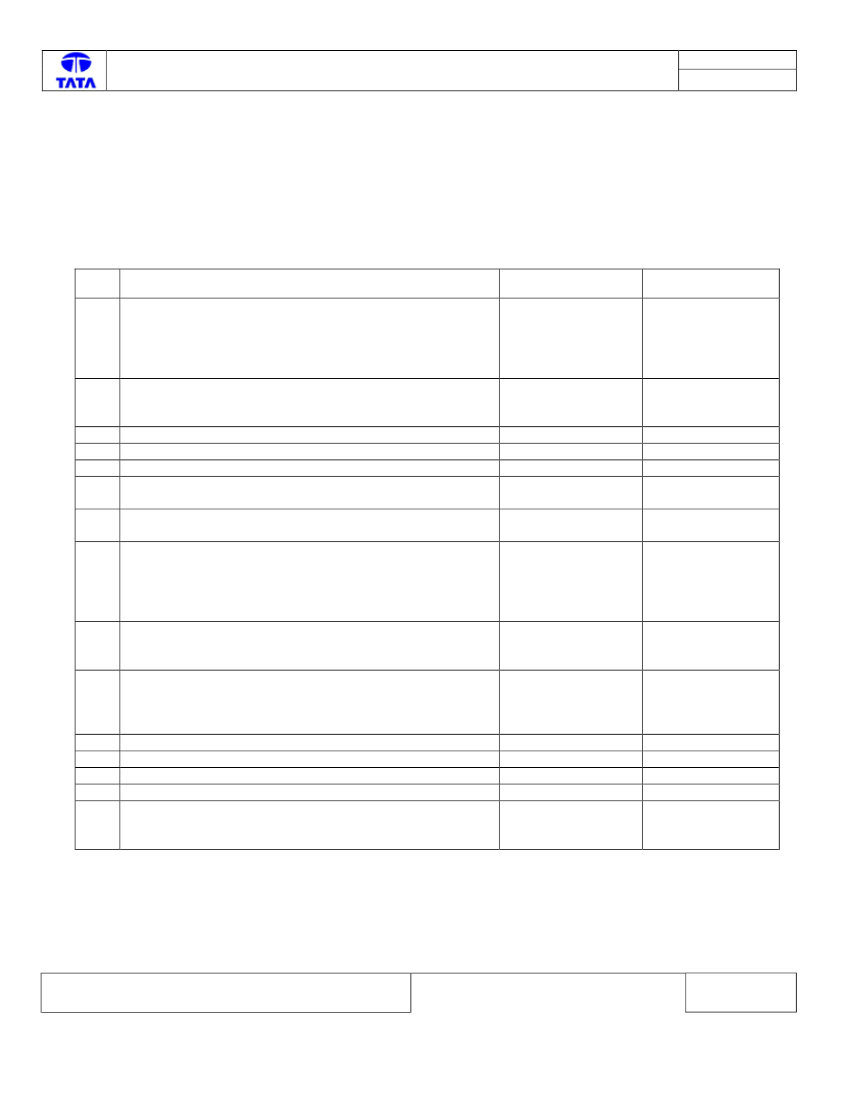
Trouble Shooting:
Step Checks
IF YES
IF NO
1
Is there wiring harness electrical continuity between ECU
pin A037 & Cam Shaft sensor pin 3, ECU pin A052 and
Cam shaft sensor pin 2, ECU pin A051 and Cam shaft
sensor pin 1.
Go to next step
Rectify the wiring
harness
connections as per
the circuit
schematic.
2
Check whether the ECM pins A037, A052, A051 are either
short circuited to Battery Supply / Ground
Request Driver on
not to over-speed
vehicle
Go to next step
3
Check whether the cam shaft sensor is damaged
Call hotline
Go to Next Step
4
Check whether the Camshaft is damaged
Replace camshaft
Go to next step
5
Check whether the Crankshaft is damaged
Replace crankshaft
Go to next step
6
Are there any pins backed out from the Cam shaft sensor
Connector
Rectify/Replace
Connectors
Go to Next Step
7
Are there any pins backed out from the EMS ECU
Connector
Rectify/Replace
Connectors
Go to Next Step
8
Is there wiring harness electrical continuity between ECU
pin A020 & Crank Shaft sensor pin 1, ECU pin A021 and
Crank shaft sensor pin 2.
Go to next step
Rectify the wiring
harness
connections as per
the circuit
schematic.
9
Check whether the ECM pins A020 or A021 are either short
circuited to Battery / Ground / Open circuited.
Rectify the wiring
harness connections
as per the schematic
Go to Next Step
10
Check whether the air gap between the magnets and
sensing element of Cam sensor and Crank sensor are as
per specification.
Go to next step
If not, change
mounting to align
the air gap as per
the specification.
11 Check for Misaligned timing chain
Rectify the same
Go to Next Step
12 Check for Damaged crankshaft timing teeth
Rectify the same
Go to Next Step
13 Check for Damaged camshaft timing sprocket
Rectify the same
Go to Next Step
14 Check whether Crankshaft position sensor is defective
Rectify the same
Go to Next Step
15 Fault Persists.
Call Hotline
Repeat the above
steps for re-
confirmation
DTC’s confirmation:
After rectification, Test Drive the vehicle for 2 KM and ensure that no DTC’s are logged in ECM.