


 4036 / 4910

{Osprey CCM}
DTC Troubleshooting Data
Version: 2.0
Date: 28-Jul-17
Author: ERC
Page: 220 of 244
Copyright ©
TATA MOTORS Ltd.
This document must not be used in any way, such as copying and redistributing to third parties, without the consent of author.
DTC’s confirmation:-
After rectification, ensure the following points using TML diagnostic tool before handing over to customer.
a) Check whether HVAC ECU is communicating with diagnostic Tool or not.
b) DTC should not be present in ECU memory.
Circuit Schematic
Diagram:-N.AComponent Location & Image:- N.A
Connector Location: N.A
Connector View & Information: - N.A
Inspection Method: - N.A
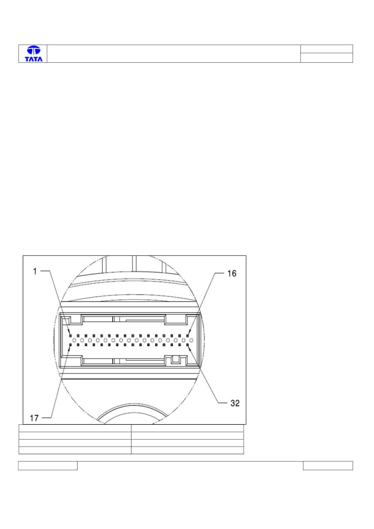
IPC ECU side connector diagram
ECU Side Connector:
IPC ECU Pin assignment:-
Description
ECU pin
CAN_H chassis
6
CAN_L chassis
5
Battery
1