


 2128 / 4910

Vehicle Platform: OSPREY
ECU Name: Hella Body Control Module (BCM) DTC
Troubleshooting Data
Version: 1.4
Date: 15 May 2018
Author: Body CoC
Page: 48 of 855
Copyright ©
TATA MOTORS Ltd.
This document must not be used in any way, such as copying and redistributing to third parties, without the consent of author.
DTC’s confirmation:-
After rectification, ensure the following points using TML diagnostic tool before handing over to customer.
a) Check whether SRS ECU is communicating with diagnostic Tool or not.
b) DTC should not be present in ECU memory.
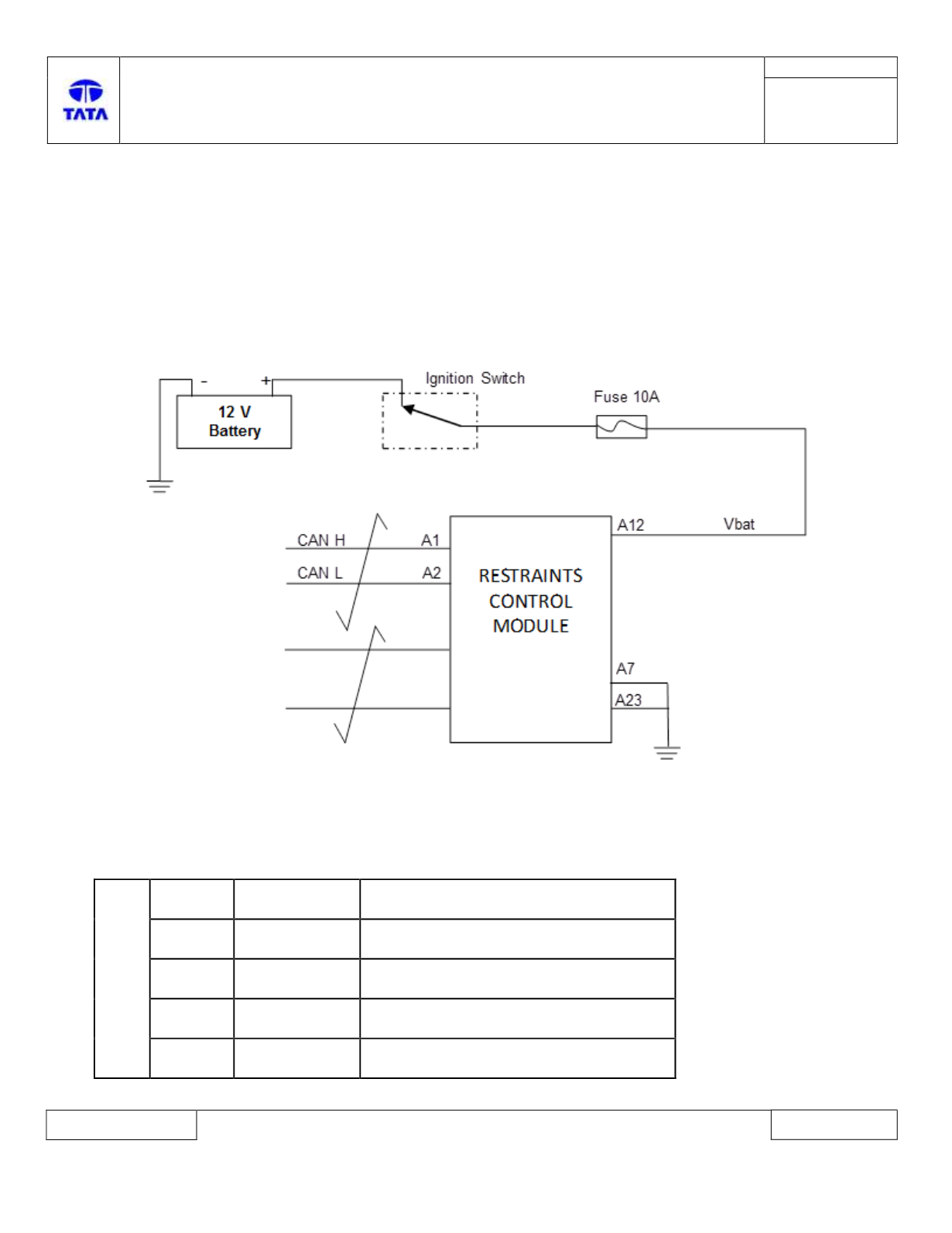
Circuit Schematic Diagram:-
SRS ECU side Connector:
Component Location & Image:- N.A
Connector Location: N.A
SRS ECU Pin assignment:-
CHAMBER A
Pin No.
Pin Name
Description
1
CAN_H
CAN High
2
CAN_L
CAN Low
7
A_GND
Common Switch GND
12
Vbat
Supply Voltage Battery